Toyota CH-R Service Manual: Room Temperature Sensor
Components
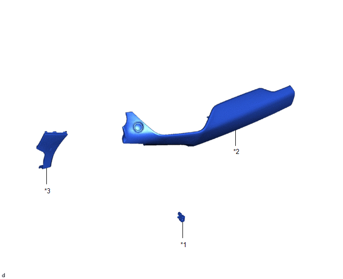
COMPONENTS
ILLUSTRATION
|
*1 |
COOLER THERMISTOR (ROOM TEMPERATURE SENSOR) |
*2 |
INSTRUMENT CLUSTER FINISH PANEL GARNISH ASSEMBLY |
|
*3 |
INSTRUMENT PANEL LOWER CENTER FINISH PANEL |
- |
- |
Inspection
INSPECTION
PROCEDURE
1. INSPECT COOLER THERMISTOR (ROOM TEMPERATURE SENSOR)
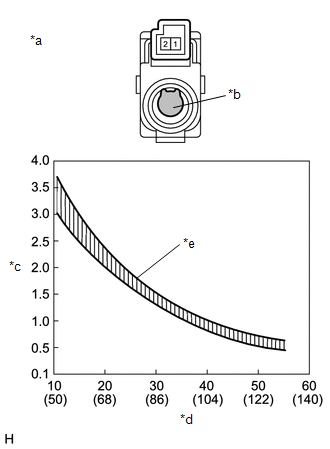
(a) Check the resistance.
|
(1) Measure the resistance according to thevalue(s) in the table below. Standard Resistance:
NOTICE:
HINT: As the temperature increases, the resistance decreases (see the graph). If the result is not as specified, replace the cooler thermistor (room temperature sensor). |
|
Removal
REMOVAL
PROCEDURE
1. REMOVE INSTRUMENT CLUSTER FINISH PANEL GARNISH ASSEMBLY
Click here
.gif)
2. REMOVE INSTRUMENT PANEL LOWER CENTER FINISH PANEL
Click here
3. REMOVE COOLER THERMISTOR (ROOM TEMPERATURE SENSOR)
|
(a) Disconnect the connector. |
|
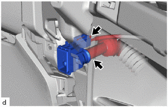
(b) Disconnect the air conditioning duct sub-assembly to remove the cooler thermistor (room temperature sensor).
Installation
INSTALLATION
PROCEDURE
1. INSTALL COOLER THERMISTOR (ROOM TEMPERATURE SENSOR)
(a) Connect the air conditioning duct sub-assembly to install the cooler thermistor (room temperature sensor).
(b) Connect the connector.
2. INSTALL INSTRUMENT PANEL LOWER CENTER FINISH PANEL
Click here
.gif)
3. INSTALL INSTRUMENT CLUSTER FINISH PANEL GARNISH ASSEMBLY
Click here
 Relay
Relay
On-vehicle Inspection
ON-VEHICLE INSPECTION
PROCEDURE
1. INSPECT PTC HEATER RELAY
(a) Check the resistance.
(1) Measure the resistance according to the value(s) in the table below.
...
 Solar Sensor
...
Other materials:
Toyota CH-R Service Manual > Hazard Warning Switch: Inspection
INSPECTION
PROCEDURE
1. INSPECT HAZARD WARNING SIGNAL SWITCH ASSEMBLY
(a) Check the resistance.
(1) Measure the resistance according to the value(s) in the table below.
Standard Resistance:
Tester Connection
Condition
Specified ...
Toyota CH-R Service Manual > Smart Key System(for Entry Function): Diagnosis System
DIAGNOSIS SYSTEM
DESCRIPTION
(a) Smart key system (for Entry Function) data and Diagnostic Trouble Codes (DTCs)
can be read through the vehicle Data Link Connector 3 (DLC3). In some cases, a malfunction
may be occurring in the smart key system. When the system seems to be malfunctioning,
use ...
Toyota C-HR (AX20) 2023-2026 Owner's Manual
Toyota CH-R Owners Manual
- For safety and security
- Instrument cluster
- Operation of each component
- Driving
- Interior features
- Maintenance and care
- When trouble arises
- Vehicle specifications
- For owners
Toyota CH-R Service Manual
- Introduction
- Maintenance
- Audio / Video
- Cellular Communication
- Navigation / Multi Info Display
- Park Assist / Monitoring
- Brake (front)
- Brake (rear)
- Brake Control / Dynamic Control Systems
- Brake System (other)
- Parking Brake
- Axle And Differential
- Drive Shaft / Propeller Shaft
- K114 Cvt
- 3zr-fae Battery / Charging
- Networking
- Power Distribution
- Power Assist Systems
- Steering Column
- Steering Gear / Linkage
- Alignment / Handling Diagnosis
- Front Suspension
- Rear Suspension
- Tire / Wheel
- Tire Pressure Monitoring
- Door / Hatch
- Exterior Panels / Trim
- Horn
- Lighting (ext)
- Mirror (ext)
- Window / Glass
- Wiper / Washer
- Door Lock
- Heating / Air Conditioning
- Interior Panels / Trim
- Lighting (int)
- Meter / Gauge / Display
- Mirror (int)
- Power Outlets (int)
- Pre-collision
- Seat
- Seat Belt
- Supplemental Restraint Systems
- Theft Deterrent / Keyless Entry

0.0065