Toyota CH-R Service Manual: 3zr-fae Drive Belt
Components
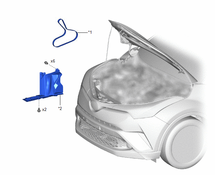
COMPONENTS
ILLUSTRATION
|
*1 |
FAN AND GENERATOR V BELT |
*2 |
REAR ENGINE UNDER COVER RH |
Removal
REMOVAL
PROCEDURE
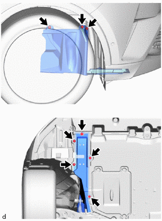
1. REMOVE REAR ENGINE UNDER COVER RH
|
(a) Remove the 2 screws, 6 clips and rear engine under cover RH from the vehicle. |
|
2. REMOVE FAN AND GENERATOR V BELT
|
(a) Attach a wrench to the hexagonal portion (A) or (B) of the V-ribbed belt tensioner assembly as shown in the illustration. |
|
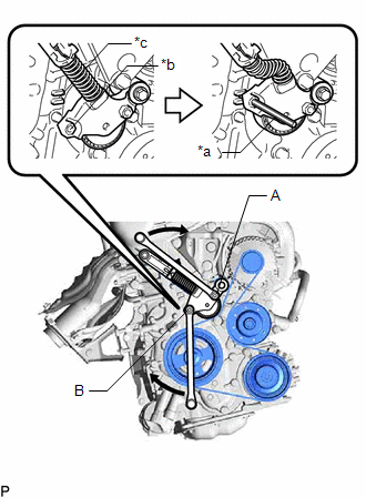
(b) Rotate the V-ribbed belt tensioner assembly clockwise to align the hole with the gap, and then insert a 5 mm bi-hexagon wrench into the hole and gap to secure the V-ribbed belt tensioner assembly.
(c) Remove the fan and generator V belt from the V-ribbed belt tensioner assembly.
Installation
INSTALLATION
PROCEDURE
1. INSTALL FAN AND GENERATOR V BELT
|
(a) Set the fan and generator V belt onto every pulley. |
|
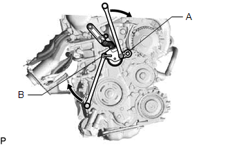
(b) Attach a wrench to the hexagonal portion (A) or (B) of the V-ribbed belt tensioner assembly as shown in the illustration, and while rotating the V-ribbed belt tensioner assembly clockwise, remove the 5 mm bi-hexagon wrench.
NOTICE:
Check that the fan and generator V belt is properly set to each pulley.
2. INSPECT FAN AND GENERATOR V BELT
Click here
.gif)
3. INSTALL REAR ENGINE UNDER COVER RH
(a) Install the rear engine under cover RH to the vehicle with the 2 screws and 6 clips.
 Replacement
REPLACEMENT
PROCEDURE
1. REMOVE NO. 1 ENGINE UNDER COVER
Click here
2. DRAIN ENGINE COOLANT
CAUTION:
When engine coolant is hot, do not remove the reserve tank cap, air
release ...

Other materials:
Toyota CH-R Service Manual > Lighting System: Headlamp LH Circuit (B2439,B243A)
DESCRIPTION
A DTC is stored when the headlight ECU sub-assembly receives a light source malfunction
signal from its respective headlight unit. The headlight ECU sub-assembly LH stores
DTC B2439 or B243A.
DTC No.
Detection Item
DTC Detection Condition
...
Toyota CH-R Service Manual > Vehicle Stability Control System: Steering Angle Sensor Internal Circuit (C1433)
DESCRIPTION
This DTC is stored when the skid control ECU (brake actuator assembly) receives
an internal malfunction signal from the steering angle sensor.
DTC No.
Detection Item
DTC Detection Condition
Trouble Area
C1433
Ste ...
Toyota C-HR (AX20) 2023-2026 Owner's Manual
Toyota CH-R Owners Manual
- For safety and security
- Instrument cluster
- Operation of each component
- Driving
- Interior features
- Maintenance and care
- When trouble arises
- Vehicle specifications
- For owners
Toyota CH-R Service Manual
- Introduction
- Maintenance
- Audio / Video
- Cellular Communication
- Navigation / Multi Info Display
- Park Assist / Monitoring
- Brake (front)
- Brake (rear)
- Brake Control / Dynamic Control Systems
- Brake System (other)
- Parking Brake
- Axle And Differential
- Drive Shaft / Propeller Shaft
- K114 Cvt
- 3zr-fae Battery / Charging
- Networking
- Power Distribution
- Power Assist Systems
- Steering Column
- Steering Gear / Linkage
- Alignment / Handling Diagnosis
- Front Suspension
- Rear Suspension
- Tire / Wheel
- Tire Pressure Monitoring
- Door / Hatch
- Exterior Panels / Trim
- Horn
- Lighting (ext)
- Mirror (ext)
- Window / Glass
- Wiper / Washer
- Door Lock
- Heating / Air Conditioning
- Interior Panels / Trim
- Lighting (int)
- Meter / Gauge / Display
- Mirror (int)
- Power Outlets (int)
- Pre-collision
- Seat
- Seat Belt
- Supplemental Restraint Systems
- Theft Deterrent / Keyless Entry

0.0072