Toyota CH-R Service Manual: Replacement
REPLACEMENT
PROCEDURE
1. RECOVER REFRIGERANT FROM REFRIGERATION SYSTEM
(a) Start the engine.
(b) Operate the compressor under the conditions shown below:
|
Item |
Condition |
|---|---|
|
Operating time |
3 minutes or more |
|
Temperature setting |
Max cool |
|
Blower speed |
High |
|
Engine |
Idling |
|
A/C switch |
On |
This causes most of the compressor oil from the various components of the A/C system to collect in the compressor.
HINT:
It is not necessary to operate the compressor if the A/C does not operate because of compressor lock, etc.
(c) Stop the engine.
(d) Recover the refrigerant from the A/C system using a refrigerant recovery unit.
HINT:
Use the refrigerant recovery unit in accordance with the manufacturer's instruction manual.
2. CHARGE AIR CONDITIONING SYSTEM WITH REFRIGERANT
(a) Perform vacuum purging using a vacuum pump or appropriate equipment.
(b) Charge the air conditioning system with refrigerant.
Refrigerant Type:
HFC-134a (R134a)
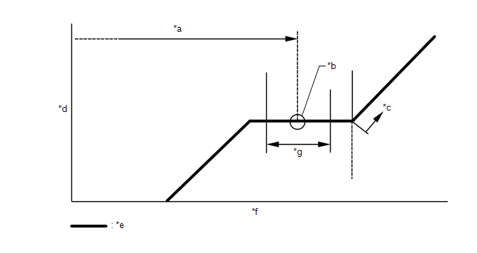
|
*a |
Standard Charge Amount |
*b |
Mean Value in Proper Range |
|
*c |
Overcharged |
*d |
High Pressure |
|
*e |
Sub-cool System |
*f |
Refrigerant Amount |
|
*g |
+/-30 g (+/-1.05 oz) |
- |
- |
Standard Charge Amount:
380 to 440 g (13.4 to 15.5 oz)
SST: 09985-20010
09985-02010
09985-02050
09985-02060
09985-02070
09985-02080
09985-02090
09985-02110
09985-02130
09985-02140
09985-02150
NOTICE:
- Do not turn the A/C switch on before charging the air conditioning system with refrigerant. Doing so may cause the compressor to work without refrigerant, resulting in overheating of the compressor.
- The refrigerant amount should be checked by quantity (weight).
- The graph above is shown for reference only.
HINT:
Ensure that sufficient refrigerant is available to recharge the system when using a refrigerant recovery unit. Refrigerant recovery units are not always able to recover 100% of the refrigerant from an air conditioning system.
3. WARM UP ENGINE
(a) Keep the A/C switch on for at least 2 minutes to warm up the compressor.
NOTICE:
To prevent damage to the compressor, be sure to warm up the compressor when turning the air conditioning on after removing and installing any air conditioning system lines (including the compressor).
4. INSPECT FOR REFRIGERANT LEAK
(a) After recharging the air conditioning system with refrigerant, inspect for refrigerant leaks using a halogen leak detector.
(b) Carry out the test under the following conditions:
- Turn the ignition switch off.
- Ensure good ventilation (the halogen leak detector may react to volatile gases which are not refrigerant, such as gasoline vapor and exhaust gas).
- Repeat the inspection 2 or 3 times.
- Measure the pressure to make sure that there is some refrigerant remaining
in the air conditioning system.
Pressure when the compressor is off: approximately 392 to 588 kPa (3.9 to 5.9 kgf/cm2, 57 to 85 psi)
|
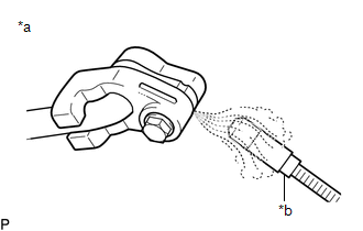
(c) Using a halogen leak detector, inspect for refrigerant leaks from the air conditioning system. |
|
|
(d) Bring the halogen leak detector close to the drain cooler hose with the detector power off, and then turn the detector on. HINT:
|
|
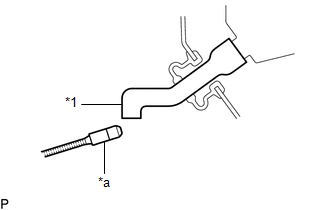
(e) If a refrigerant leak is not detected from the drain cooler hose, remove the blower motor control from the cooling unit. Insert the halogen leak detector sensor into the unit and check for leaks.
(f) Disconnect the pressure sensor connector and leave it for approximately 20 minutes. Bring the halogen leak detector close to the pressure sensor and check for leaks.
HINT:
When checking for leaks, the presence of oily dirt at a joint can indicate a leak.
 On-vehicle Inspection
ON-VEHICLE INSPECTION
PROCEDURE
1. INSPECT REFRIGERANT PRESSURE WITH MANIFOLD GAUGE SET
HINT:
The following examples show the readings of a manifold gauge set and the corresponding
air condition ...

Other materials:
Toyota CH-R Service Manual > Lighting (int): Room Light Bulb
Replacement
REPLACEMENT
PROCEDURE
1. REMOVE NO. 2 ROOM LIGHT BULB
(a) Using a screwdriver with its tip wrapped in protective tape, disengage the
claws to remove the room light lens as shown in the illustration.
*a
Protective Tape
Remove in t ...
Toyota CH-R Owners Manual > Using the driving support systems: Driving mode select
In response to driving conditions, one of 3 drive modes can be selected.
Select the drive mode
■ Changing the driving mode To select the drive mode, perform
operations on the multi-information display.
1. Press
or
of meter control switches and select
.
2. Press
or
of the met ...
Toyota C-HR (AX20) 2023-2026 Owner's Manual
Toyota CH-R Owners Manual
- For safety and security
- Instrument cluster
- Operation of each component
- Driving
- Interior features
- Maintenance and care
- When trouble arises
- Vehicle specifications
- For owners
Toyota CH-R Service Manual
- Introduction
- Maintenance
- Audio / Video
- Cellular Communication
- Navigation / Multi Info Display
- Park Assist / Monitoring
- Brake (front)
- Brake (rear)
- Brake Control / Dynamic Control Systems
- Brake System (other)
- Parking Brake
- Axle And Differential
- Drive Shaft / Propeller Shaft
- K114 Cvt
- 3zr-fae Battery / Charging
- Networking
- Power Distribution
- Power Assist Systems
- Steering Column
- Steering Gear / Linkage
- Alignment / Handling Diagnosis
- Front Suspension
- Rear Suspension
- Tire / Wheel
- Tire Pressure Monitoring
- Door / Hatch
- Exterior Panels / Trim
- Horn
- Lighting (ext)
- Mirror (ext)
- Window / Glass
- Wiper / Washer
- Door Lock
- Heating / Air Conditioning
- Interior Panels / Trim
- Lighting (int)
- Meter / Gauge / Display
- Mirror (int)
- Power Outlets (int)
- Pre-collision
- Seat
- Seat Belt
- Supplemental Restraint Systems
- Theft Deterrent / Keyless Entry

0.0111