Toyota CH-R Service Manual: Ion Generator
Components
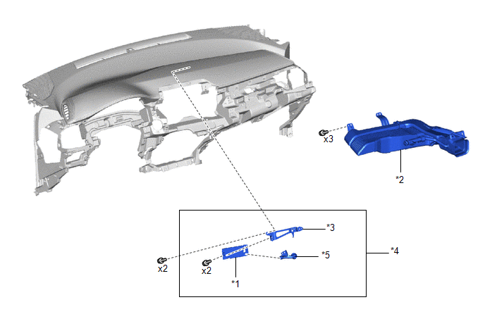
COMPONENTS
ILLUSTRATION
|
*1 |
ION GENERATOR SUB-ASSEMBLY |
*2 |
NO. 1 HEATER TO REGISTER DUCT SUB-ASSEMBLY |
|
*3 |
NO. 1 ION GENERATOR BRACKET |
*4 |
ION GENERATOR SUB-ASSEMBLY WITH NO. 1 ION GENERATOR BRACKET |
|
*5 |
AIR DUCT SUB-ASSEMBLY |
- |
- |
Installation
INSTALLATION
PROCEDURE
1. INSTALL ION GENERATOR SUB-ASSEMBLY
(a) Install the ion generator sub-assembly and air duct sub-assembly to the No. 1 ion generator bracket with the 2 screws.
(b) Install the ion generator sub-assembly with No. 1 ion generator bracket with the 2 scews.
(c) Disconnect the connector.
2. INSTALL NO. 1 HEATER TO REGISTER DUCT SUB-ASSEMBLY
Click here
.gif)
3. INSTALL INSTRUMENT PANEL SAFETY PAD ASSEMBLY
Click here
Removal
REMOVAL
CAUTION / NOTICE / HINT
The necessary procedures (adjustment, calibration, initialization or registration) that must be performed after parts are removed, installed or replaced during the ion generator (for Front Side) removal/installation are shown below.
Necessary Procedures after parts removed / installed / replaced|
Replacement Part or Procedure |
Necessary Procedures |
Effects / Inoperative when not performed |
Link |
|---|---|---|---|
|
Disconnect cable from negative battery terminal |
Initialize back door lock |
Power door lock control system |
|
|
Memorize steering angle neutral point |
Lane departure alert system (w/ Steering Control) |
|
|
|
Pre-collision system |
CAUTION:
Some of these service operations affect the SRS airbag system. Read the precautionary notices concerning the SRS airbag system before servicing.
.png)
Click here
.gif)
PROCEDURE
1. REMOVE INSTRUMENT PANEL SAFETY PAD ASSEMBLY
Click here
2. REMOVE NO. 1 HEATER TO REGISTER DUCT SUB-ASSEMBLY
Click here
3. REMOVE ION GENERATOR SUB-ASSEMBLY
|
(a) Disconnect the connector. |
|
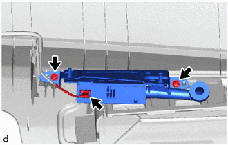
(b) Remove the 2 screws and ion generator sub-assembly with No. 1 ion generator bracket.
|
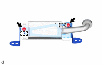
(c) Remove the 2 screws, ion generator sub-assembly and air duct sub-assembly from the No. 1 ion generator bracket. |
|
 Installation
INSTALLATION
PROCEDURE
1. INSTALL NO. 1 COOLER THERMISTOR
(a) Install the No. 1 cooler thermistor.
HINT:
Install the No. 1 cooler thermistor in the same area as the one that was previously
inst ...

Other materials:
Toyota CH-R Service Manual > Front Seat Cushion Heater: Components
COMPONENTS
ILLUSTRATION
*1
SEPARATE TYPE FRONT SEAT CUSHION COVER WITH PAD
-
-
ILLUSTRATION
*1
FRONT SEAT CUSHION HEATER ASSEMBLY
*2
SEPARATE TYPE FRONT SEAT CUSHION COVER
*3
...
Toyota CH-R Service Manual > Power Window Control System: Diagnosis System
DIAGNOSIS SYSTEM
DESCRIPTION
(a) Power window control system data and Diagnostic Trouble Codes (DTCs) can
be read through the vehicle Data Link Connector 3 (DLC3). When the system seems
to be malfunctioning, use the Techstream to check for malfunctions and perform repairs.
CHECK DLC3
(a) Che ...
Toyota C-HR (AX20) 2023-2026 Owner's Manual
Toyota CH-R Owners Manual
- For safety and security
- Instrument cluster
- Operation of each component
- Driving
- Interior features
- Maintenance and care
- When trouble arises
- Vehicle specifications
- For owners
Toyota CH-R Service Manual
- Introduction
- Maintenance
- Audio / Video
- Cellular Communication
- Navigation / Multi Info Display
- Park Assist / Monitoring
- Brake (front)
- Brake (rear)
- Brake Control / Dynamic Control Systems
- Brake System (other)
- Parking Brake
- Axle And Differential
- Drive Shaft / Propeller Shaft
- K114 Cvt
- 3zr-fae Battery / Charging
- Networking
- Power Distribution
- Power Assist Systems
- Steering Column
- Steering Gear / Linkage
- Alignment / Handling Diagnosis
- Front Suspension
- Rear Suspension
- Tire / Wheel
- Tire Pressure Monitoring
- Door / Hatch
- Exterior Panels / Trim
- Horn
- Lighting (ext)
- Mirror (ext)
- Window / Glass
- Wiper / Washer
- Door Lock
- Heating / Air Conditioning
- Interior Panels / Trim
- Lighting (int)
- Meter / Gauge / Display
- Mirror (int)
- Power Outlets (int)
- Pre-collision
- Seat
- Seat Belt
- Supplemental Restraint Systems
- Theft Deterrent / Keyless Entry

0.008