Toyota CH-R Service Manual: Components
COMPONENTS
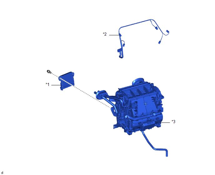
ILLUSTRATION
|
*1 |
AIR CONDITIONING AMPLIFIER ASSEMBLY |
*2 |
AIR CONDITIONING HARNESS ASSEMBLY |
|
*3 |
HEATER RADIATOR UNIT SUB-ASSEMBLY |
- |
- |
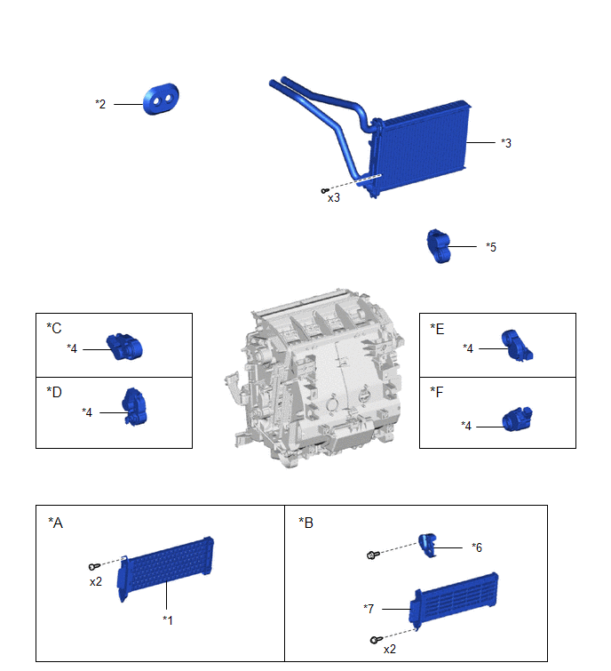
ILLUSTRATION
|
*A |
w/o PTC Heater |
*B |
w/ PTC Heater |
|
*C |
for Upper LH Side |
*D |
for Lower LH Side |
|
*E |
for Upper RH Side |
*F |
for Lower RH Side |
|
*1 |
HEATER COVER |
*2 |
HEATER PIPE GROMMET |
|
*3 |
HEATER RADIATOR UNIT SUB-ASSEMBLY |
*4 |
NO. 1 AIR CONDITIONING RADIATOR DAMPER SERVO SUB-ASSEMBLY |
|
*5 |
NO. 2 AIR CONDITIONING RADIATOR DAMPER SERVO SUB-ASSEMBLY |
*6 |
NO. 2 HEATER COVER |
|
*7 |
QUICK HEATER ASSEMBLY |
- |
- |
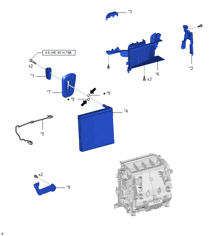
ILLUSTRATION
|
*1 |
COOLER EXPANSION VALVE |
*2 |
HEAT EXCHANGER CASE |
|
*3 |
HEATER CLAMP |
*4 |
NO. 1 COOLER EVAPORATOR SUB-ASSEMBLY |
|
*5 |
NO. 1 COOLER THERMISTOR |
*6 |
RADIATOR CASE SUB-ASSEMBLY |
|
*7 |
GROMMET |
*8 |
BRACKET |
|
*9 |
O-RING |
- |
- |
.png) |
N*m (kgf*cm, ft.*lbf): Specified torque |
● |
Non-reusable part |
.png) |
Compressor oil VC 100YF or equivalent |
- |
- |

 Removal
REMOVAL
CAUTION / NOTICE / HINT
The necessary procedures (adjustment, calibration, initialization or registration)
that must be performed after parts are removed and installed, or replaced during ...
Other materials:
Toyota CH-R Service Manual > Power Window Control System: All Power Windows do not Operate with Driver Side Door Key Cylinder or Wireless
Transmitter
DESCRIPTION
Wireless Transmitter-linked Function
w/ Smart Key System:
When an electronic key transmitter sub-assembly switch is pushed:
1) the door control receiver receives the wireless door lock signal;
2) the door control receiver sends a signal to the main bod ...
Toyota CH-R Service Manual > Steering Lock System: Problem Symptoms Table
PROBLEM SYMPTOMS TABLE
HINT:
Use the table below to help determine the cause of problem symptoms.
If multiple suspected areas are listed, the potential causes of the symptoms
are listed in order of probability in the "Suspected Area" column of the
table. Check each sy ...
Toyota C-HR (AX20) 2023-2026 Owner's Manual
Toyota CH-R Owners Manual
- For safety and security
- Instrument cluster
- Operation of each component
- Driving
- Interior features
- Maintenance and care
- When trouble arises
- Vehicle specifications
- For owners
Toyota CH-R Service Manual
- Introduction
- Maintenance
- Audio / Video
- Cellular Communication
- Navigation / Multi Info Display
- Park Assist / Monitoring
- Brake (front)
- Brake (rear)
- Brake Control / Dynamic Control Systems
- Brake System (other)
- Parking Brake
- Axle And Differential
- Drive Shaft / Propeller Shaft
- K114 Cvt
- 3zr-fae Battery / Charging
- Networking
- Power Distribution
- Power Assist Systems
- Steering Column
- Steering Gear / Linkage
- Alignment / Handling Diagnosis
- Front Suspension
- Rear Suspension
- Tire / Wheel
- Tire Pressure Monitoring
- Door / Hatch
- Exterior Panels / Trim
- Horn
- Lighting (ext)
- Mirror (ext)
- Window / Glass
- Wiper / Washer
- Door Lock
- Heating / Air Conditioning
- Interior Panels / Trim
- Lighting (int)
- Meter / Gauge / Display
- Mirror (int)
- Power Outlets (int)
- Pre-collision
- Seat
- Seat Belt
- Supplemental Restraint Systems
- Theft Deterrent / Keyless Entry

0.0082