Toyota CH-R Service Manual: Components
COMPONENTS
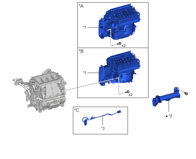
ILLUSTRATION
|
*A |
for Dual Type |
*B |
for Single Type |
|
*C |
w/ PTC Heater |
- |
- |
|
*1 |
BLOWER ASSEMBLY |
*2 |
NO. 2 AIR DUCT |
|
*3 |
NO. 3 INSTRUMENT PANEL WIRE |
- |
- |
|
● |
Non-reusable part |
- |
- |
ILLUSTRATION
|
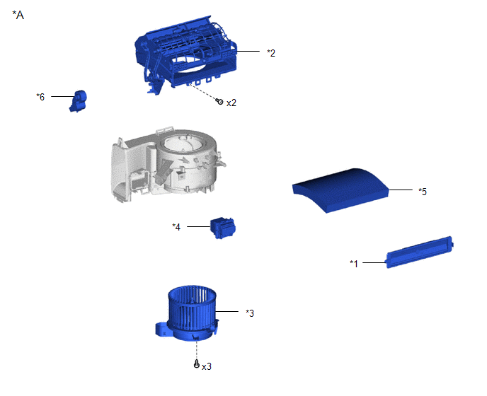
*A |
for Single Type |
- |
- |
|
*1 |
AIR FILTER COVER PLATE |
*2 |
AIR FILTER SUB-ASSEMBLY |
|
*3 |
BLOWER MOTOR WITH FAN SUB-ASSEMBLY |
*4 |
BLOWER RESISTOR |
|
*5 |
CLEAN AIR FILTER |
*6 |
NO. 1 BLOWER DAMPER SERVO SUB-ASSEMBLY |
ILLUSTRATION
|
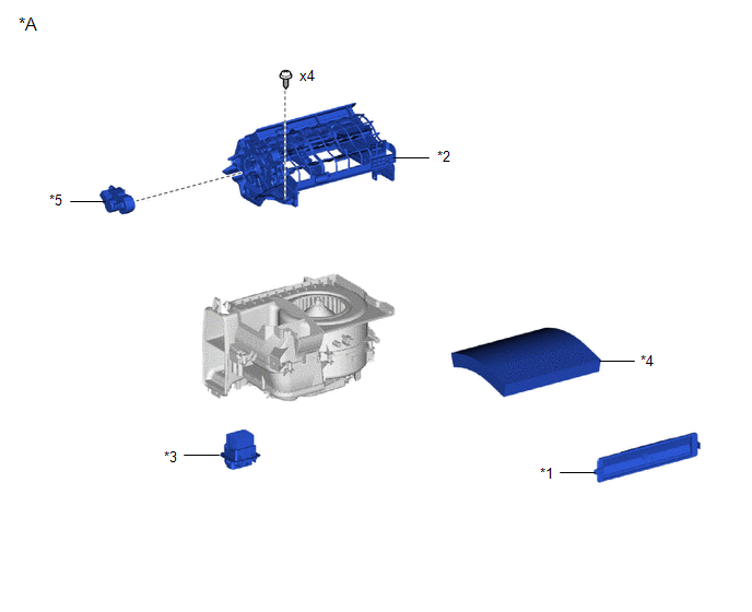
*A |
for Dual Type |
- |
- |
|
*1 |
AIR FILTER COVER PLATE |
*2 |
AIR FILTER SUB-ASSEMBLY |
|
*3 |
BLOWER RESISTOR |
*4 |
CLEAN AIR FILTER |
|
*5 |
NO. 1 BLOWER DAMPER SERVO SUB-ASSEMBLY |
- |
- |

 Removal
REMOVAL
CAUTION / NOTICE / HINT
The necessary procedures (adjustment, calibration, initialization, or registration)
that must be performed after parts are removed, installed, or replaced during th ...
Other materials:
Toyota CH-R Service Manual > Air Conditioning System(for Automatic Air Conditioning System With Top-mounted
Air Conditioner Pressure Sensor): Lost Communication with ECM (U0100-U0142,U0155)
DESCRIPTION
DTC No.
Detection Item
DTC Detection Condition
Trouble Area
Memory
U0100
Lost Communication with ECM
No communication with ECM
CAN communication system
ECM
...
Toyota CH-R Service Manual > Revolution Sensor: Components
COMPONENTS
ILLUSTRATION
*1
AIR CLEANER CAP WITH AIR CLEANER HOSE
*2
AIR CLEANER CASE SUB-ASSEMBLY
*3
BATTERY CLAMP SUB-ASSEMBLY
*4
ECM
*5
NO. 1 AIR CLEANER INLET
* ...
Toyota C-HR (AX20) 2023-2026 Owner's Manual
Toyota CH-R Owners Manual
- For safety and security
- Instrument cluster
- Operation of each component
- Driving
- Interior features
- Maintenance and care
- When trouble arises
- Vehicle specifications
- For owners
Toyota CH-R Service Manual
- Introduction
- Maintenance
- Audio / Video
- Cellular Communication
- Navigation / Multi Info Display
- Park Assist / Monitoring
- Brake (front)
- Brake (rear)
- Brake Control / Dynamic Control Systems
- Brake System (other)
- Parking Brake
- Axle And Differential
- Drive Shaft / Propeller Shaft
- K114 Cvt
- 3zr-fae Battery / Charging
- Networking
- Power Distribution
- Power Assist Systems
- Steering Column
- Steering Gear / Linkage
- Alignment / Handling Diagnosis
- Front Suspension
- Rear Suspension
- Tire / Wheel
- Tire Pressure Monitoring
- Door / Hatch
- Exterior Panels / Trim
- Horn
- Lighting (ext)
- Mirror (ext)
- Window / Glass
- Wiper / Washer
- Door Lock
- Heating / Air Conditioning
- Interior Panels / Trim
- Lighting (int)
- Meter / Gauge / Display
- Mirror (int)
- Power Outlets (int)
- Pre-collision
- Seat
- Seat Belt
- Supplemental Restraint Systems
- Theft Deterrent / Keyless Entry

0.0073