Toyota CH-R Service Manual: Reassembly
REASSEMBLY
PROCEDURE
1. INSTALL NO. 1 COOLER THERMISTOR
Click here
.gif)
2. INSTALL NO. 2 RADIATOR CASE SUB-ASSEMBLY
|
(a) Install the No. 2 radiator case sub-assembly with the 6 screws. |
|
.png)
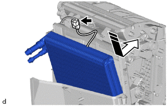
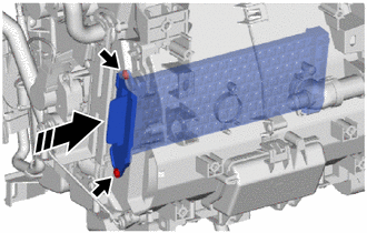
3. INSTALL NO. 1 COOLER EVAPORATOR SUB-ASSEMBLY
.png) |
Install in this Direction |
(a) Install the No. 1 cooler evaporator sub-assembly with No. 1 cooler thermistor as shown in the illustration.
(b) Connect the connector.
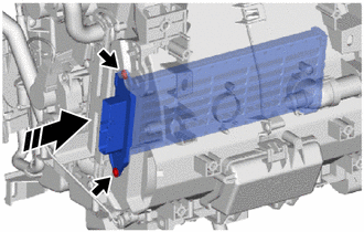
4. INSTALL RADIATOR CASE SUB-ASSEMBLY
(a) Engage the claws and to install the radiator case sub-assembly.
.png)
(b) Install the 3 screws.
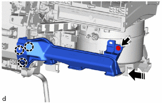
5. INSTALL HEAT EXCHANGER CASE
|
(a) Engage the 2 claws and guide, and install the heat exchanger case with the screw. |
|
.png)
|
(b) Install the bracket with the 2 screws. |
|
.png)
6. INSTALL COOLER EXPANSION VALVE
|
(a) Install the grommet. |
|
.png)
(b) Sufficiently apply compressor oil to 2 new O-rings and fitting surfaces of the No. 1 cooler evaporator sub-assembly.
Compressor Oil:
VC100YF or equivalent
(c) Install the 2 O-rings to the No. 1 cooler evaporator sub-assembly.
NOTICE:
Keep the O-rings and O-ring fitting surfaces free of foreign matter.
|
(d) Using a 4 mm hexagon socket wrench, install the cooler expansion valve with the 2 hexagon bolts. Torque: 4.5 N·m {46 kgf·cm, 40 in·lbf} |
|
.png)
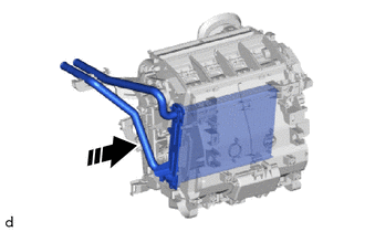
7. INSTALL HEATER RADIATOR UNIT SUB-ASSEMBLY
|
|
Install in this Direction |
(a) Install the heater radiator unit sub-assembly as shown in the illustration.
|
(b) Install the 3 screws. |
|
.png)
8. INSTALL HEATER CLAMP
|
(a) Engage the claws to install the heater clamp. |
|
.png)
(b) Install the screw.
9. INSTALL HEATER PIPE GROMMET
|
(a) Install the heater pipe grommet. |
|
.png)
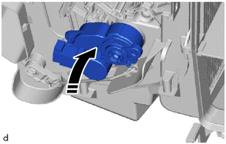
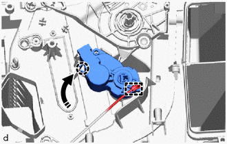
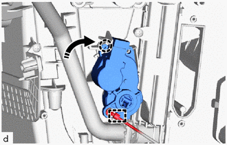
10. INSTALL NO. 2 AIR CONDITIONING RADIATOR DAMPER SERVO SUB-ASSEMBLY
(a) Install the No. 2 air conditioning radiator damper servo sub-assembly as shown in the illustration.
|
|
Install in this Direction |
(b) Turn the No. 2 air conditioning radiator damper servo sub-assembly to engage the claw as shown in the illustration.
.png)
|
|
Install in this Direction |
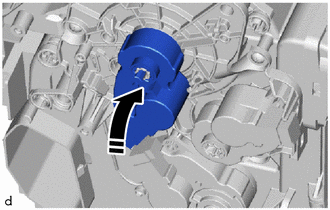
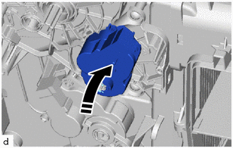
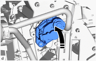
11. INSTALL NO. 1 AIR CONDITIONING RADIATOR DAMPER SERVO SUB-ASSEMBLY
(a) for Lower RH Side:
(1) Install the No. 1 air conditioning radiator damper servo sub-assembly as shown in the illustration.
|
|
Install in this Direction |
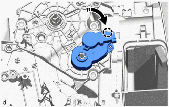
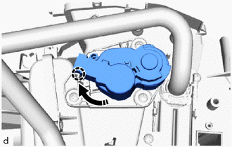
(2) Turn the No. 1 air conditioning radiator damper servo sub-assembly to engage the claw as shown in the illustration.
|
|
Install in this Direction |
(3) Engage the snap.
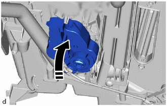
(b) for Upper RH Side:
(1) Install the No. 1 air conditioning radiator damper servo sub-assembly as shown in the illustration.
|
|
Install in this Direction |
(2) Turn the No. 1 air conditioning radiator damper servo sub-assembly to engage the claw as shown in the illustration.
|
|
Install in this Direction |
(c) for Lower LH Side:
(1) Install the No. 1 air conditioning radiator damper servo sub-assembly as shown in the illustration.
|
|
Install in this Direction |
(2) Turn the No. 1 air conditioning radiator damper servo sub-assembly to engage the claw as shown in the illustration.
|
|
Install in this Direction |
(3) Engage the snap.
(d) for Upper LH Side:
(1) Install the No. 1 air conditioning radiator damper servo sub-assembly as shown in the illustration.
|
|
Install in this Direction |
(2) Turn the No. 1 air conditioning radiator damper servo sub-assembly to engage the claw as shown in the illustration.
|
|
Install in this Direction |
12. INSTALL NO. 2 COOLER UNIT DRAIN HOSE
|
(a) Install the No. 2 cooler unit drain hose. |
|
.png)
13. INSTALL DRAIN COOLER HOSE
|
(a) Install the drain cooler hose. |
|
.png)
14. INSTALL AIR CONDITIONING HARNESS ASSEMBLY
(a) Engage clamps to install the air conditioning harness assembly.
.png)
(b) Connect the 5 connectors.
15. INSTALL AIR CONDITIONING AMPLIFIER ASSEMBLY
(a) Engage the guides to temporarily install the air conditioning amplifier assembly as shown in the illustration.
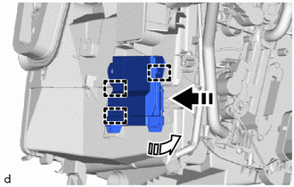
|
|
Install in this Direction (1) |
.png) |
Install in this Direction (2) |
|
(b) Install the air conditioning amplifier assembly with the screw. |
|
.png)
(c) Connect the connector.
16. INSTALL HEATER COVER (w/o PTC Heater)
(a) Install the heater cover with the 2 screws as shown in the illustration.
|
|
Install in this Direction |
17. INSTALL QUICK HEATER ASSEMBLY (w/ PTC Heater)
|
|
Install in this Direction |
(a) Install the quick heater assembly with the 2 screws as shown in the illustration.
18. INSTALL NO. 2 HEATER COVER (w/ PTC Heater)
|
(a) Install the No. 2 heater cover with the screw. |
|
.png)
19. INSTALL BLOWER ASSEMBLY
Click here
20. INSTALL NO. 3 COOLER UNIT DRAIN HOSE
|
(a) Install the No. 3 cooler unit drain hose. |
|
.png)
21. INSTALL NO. 3 INSTRUMENT PANEL WIRE (w/ PTC Heater)
|
(a) Engage the clamps to install the No. 3 instrument panel wire. |
|
.png)
(b) Connect the connector.
22. INSTALL COVER (except Cold Area Specification Vehicles)
|
(a) Engage the claws to install the cover. |
|
.png)
23. INSTALL AIR CONDITIONING DUCT SUB-ASSEMBLY
|
(a) Engage the guide to install the air conditioning duct sub-assembly. |
|
.png)
24. INSTALL NO. 2 AIR DUCT
(a) Engage the claws to install the No. 2 air duct as shown in the illustration.
|
|
Install in this Direction |
(b) Install the screw.
25. INSTALL ID CODE BOX (IMMOBILISER CODE ECU)
Click here
 Disassembly
DISASSEMBLY
PROCEDURE
1. PRECAUTION
NOTICE:
Make sure to perform initialization after replacing the air conditioning radiator
damper servo sub-assembly. If initialization is not performed, the a ...
 Installation
INSTALLATION
PROCEDURE
1. INSTALL LOWER DEFROSTER NOZZLE ASSEMBLY
(a) Engage the claws to install the lower defroster nozzle assembly.
2. ...
Other materials:
Toyota CH-R Service Manual > Safety Connect System: Dcm Operation History
DCM OPERATION HISTORY
DCM OPERATION HISTORY
This function shows the telematics network status when the DCM (Telematics Transceiver)
was operated. Use this when no DTC is present but this telematics system was unable
to connect to the call center. This symptom may occur if cell phone signal str ...
Toyota CH-R Service Manual > Wireless Door Lock Control System(w/ Smart Key System): System Diagram
SYSTEM DIAGRAM
Wireless Door Lock Control System
Communication Table
Sender
Receiver
Signal
Line
Certification ECU
(Smart Key ECU Assembly)
Main Body ECU
(Multiplex Network Body ECU)
Wireless door lock ...
Toyota C-HR (AX20) 2023-2026 Owner's Manual
Toyota CH-R Owners Manual
- For safety and security
- Instrument cluster
- Operation of each component
- Driving
- Interior features
- Maintenance and care
- When trouble arises
- Vehicle specifications
- For owners
Toyota CH-R Service Manual
- Introduction
- Maintenance
- Audio / Video
- Cellular Communication
- Navigation / Multi Info Display
- Park Assist / Monitoring
- Brake (front)
- Brake (rear)
- Brake Control / Dynamic Control Systems
- Brake System (other)
- Parking Brake
- Axle And Differential
- Drive Shaft / Propeller Shaft
- K114 Cvt
- 3zr-fae Battery / Charging
- Networking
- Power Distribution
- Power Assist Systems
- Steering Column
- Steering Gear / Linkage
- Alignment / Handling Diagnosis
- Front Suspension
- Rear Suspension
- Tire / Wheel
- Tire Pressure Monitoring
- Door / Hatch
- Exterior Panels / Trim
- Horn
- Lighting (ext)
- Mirror (ext)
- Window / Glass
- Wiper / Washer
- Door Lock
- Heating / Air Conditioning
- Interior Panels / Trim
- Lighting (int)
- Meter / Gauge / Display
- Mirror (int)
- Power Outlets (int)
- Pre-collision
- Seat
- Seat Belt
- Supplemental Restraint Systems
- Theft Deterrent / Keyless Entry

0.007