Toyota CH-R Service Manual: Blower Motor Circuit
DESCRIPTION
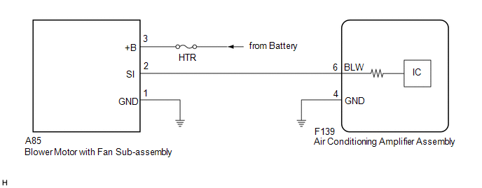
The blower motor with fan sub-assembly is operated by signals from the air conditioning amplifier assembly. Blower motor speed signals are transmitted in accordance with changes in the duty ratio.
WIRING DIAGRAM
CAUTION / NOTICE / HINT
NOTICE:
Inspect the fuses for circuits related to this system before performing the following procedure.
PROCEDURE
|
1. |
PERFORM ACTIVE TEST USING TECHSTREAM |
(a) Connect the Techstream to the DLC3.
(b) Turn the ignition switch to ON.
(c) Turn the Techstream on.
(d) Enter the following menus: Body Electrical / Air Conditioner / Active Test.
(e) Perform the Active Test according to the display on the Techstream.
Body Electrical > Air Conditioner > Active Test|
Tester Display |
Measurement Item |
Control Range |
Diagnostic Note |
|---|---|---|---|
|
Blower Motor |
Blower motor with fan sub-assembly |
Min.: 0, Max.: 31 |
- |
|
Tester Display |
|---|
|
Blower Motor |
|
Result |
Proceed to |
|---|---|
|
OK |
A |
|
NG (Blower motor with fan sub-assembly does not operate) |
B |
|
NG (Blower motor with fan sub-assembly operates but does not change speed) |
C |
| A | .gif) |
PROCEED TO NEXT SUSPECTED AREA SHOWN IN PROBLEM SYMPTOMS TABLE |
| C | |
GO TO STEP 6 |
|
.gif)
|
2. |
CHECK HARNESS AND CONNECTOR (BLOWER MOTOR WITH FAN SUB-ASSEMBLY - BODY GROUND) |
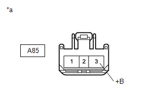
(a) Disconnect the A85 blower motor with fan sub-assembly connector.
(b) Measure the resistance according to the value(s) in the table below.
Standard Resistance:
|
Tester Connection |
Condition |
Specified Condition |
|---|---|---|
|
A85-1 (GND) - Body ground |
Always |
Below 1 Ω |
| NG | |
REPAIR OR REPLACE HARNESS OR CONNECTOR |
|
|
3. |
CHECK HARNESS AND CONNECTOR (BLOWER MOTOR WITH FAN SUB-ASSEMBLY - BATTERY) |
|
(a) Measure the voltage according to the value(s) in the table below. Standard Voltage:
|
|
| NG | |
REPAIR OR REPLACE HARNESS OR CONNECTOR |
|
|
4. |
CHECK HARNESS AND CONNECTOR (AIR CONDITIONING AMPLIFIER ASSEMBLY - BLOWER MOTOR WITH FAN SUB-ASSEMBLY) |
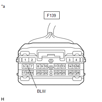
(a) Disconnect the F139 air conditioning amplifier assembly connector.
(b) Measure the resistance according to the value(s) in the table below.
Standard Resistance:
|
Tester Connection |
Condition |
Specified Condition |
|---|---|---|
|
F139-6 (BLW) - A85-2 (SI) |
Always |
Below 1 Ω |
|
F139-6 (BLW) or A85-2 (SI) - Body ground |
Always |
10 kΩ or higher |
| NG | |
REPAIR OR REPLACE HARNESS OR CONNECTOR |
|
|
5. |
INSPECT BLOWER MOTOR WITH FAN SUB-ASSEMBLY |
(a) Reconnect the A85 blower motor with fan sub-assembly connector.
|
(b) Measure the voltage according to the value(s) in the table below. Standard Voltage:
|
|
| NG | |
REPLACE BLOWER MOTOR WITH FAN SUB-ASSEMBLY |
|
|
6. |
INSPECT AIR CONDITIONING AMPLIFIER ASSEMBLY |
(a) Reconnect the F139 air conditioning amplifier assembly connector.
(b) Turn the ignition switch ON.
(c) Turn the blower switch on (LO).
|
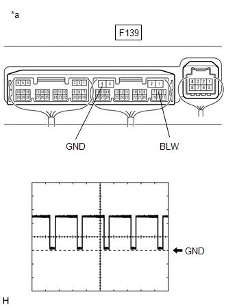
(d) Connect an oscilloscope to terminals F139-6 (BLW) and F139-4 (GND) of the air conditioning amplifier assembly and check the waveform. OK: Waveform is similar to that shown in the illustration. HINT: The waveform varies with the blower speed.
|
|
| OK | |
REPLACE BLOWER MOTOR WITH FAN SUB-ASSEMBLY |
| NG | |
REPLACE AIR CONDITIONING AMPLIFIER ASSEMBLY |
 Ambient Temperature Sensor Circuit (B1412)
DESCRIPTION
The thermistor assembly is installed in front of the cooler condenser assembly
to detect the ambient temperature, which is used to control the air conditioning
system. This sensor is ...
 PTC Heater Circuit
DESCRIPTION
The air conditioning amplifier assembly sends operation signals to the PTC heater
relays when quick heater assembly operation conditions are met. Based on the signals
from the air con ...
Other materials:
Toyota CH-R Service Manual > Wireless Door Lock Control System(w/ Smart Key System): Customize Parameters
CUSTOMIZE PARAMETERS
CUSTOMIZE WIRELESS DOOR LOCK CONTROL SYSTEM
HINT:
The following items can be customized.
NOTICE:
When the customer requests a change in a function, first make sure that
the function can be customized.
Be sure to make a note of the current settings before cus ...
Toyota CH-R Service Manual > Meter / Gauge System: Precaution
PRECAUTION
FUEL RECEIVER GAUGE OPERATION
(a) OPERATION
The combination meter assembly uses the fuel injection volume signal from the
ECM, fuel sender gauge assembly to detect the amount of fuel remaining in the fuel
tank assembly. Each gauge assembly has a variable resistor whose resistance c ...
Toyota C-HR (AX20) 2023-2026 Owner's Manual
Toyota CH-R Owners Manual
- For safety and security
- Instrument cluster
- Operation of each component
- Driving
- Interior features
- Maintenance and care
- When trouble arises
- Vehicle specifications
- For owners
Toyota CH-R Service Manual
- Introduction
- Maintenance
- Audio / Video
- Cellular Communication
- Navigation / Multi Info Display
- Park Assist / Monitoring
- Brake (front)
- Brake (rear)
- Brake Control / Dynamic Control Systems
- Brake System (other)
- Parking Brake
- Axle And Differential
- Drive Shaft / Propeller Shaft
- K114 Cvt
- 3zr-fae Battery / Charging
- Networking
- Power Distribution
- Power Assist Systems
- Steering Column
- Steering Gear / Linkage
- Alignment / Handling Diagnosis
- Front Suspension
- Rear Suspension
- Tire / Wheel
- Tire Pressure Monitoring
- Door / Hatch
- Exterior Panels / Trim
- Horn
- Lighting (ext)
- Mirror (ext)
- Window / Glass
- Wiper / Washer
- Door Lock
- Heating / Air Conditioning
- Interior Panels / Trim
- Lighting (int)
- Meter / Gauge / Display
- Mirror (int)
- Power Outlets (int)
- Pre-collision
- Seat
- Seat Belt
- Supplemental Restraint Systems
- Theft Deterrent / Keyless Entry

0.0084