Toyota CH-R Service Manual: Ambient Temperature Sensor Circuit (B1412)
DESCRIPTION
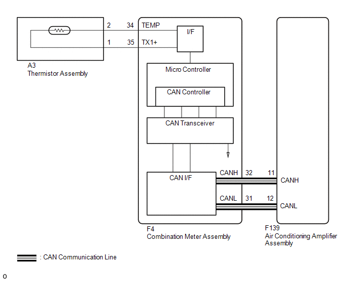
The thermistor assembly is installed in front of the cooler condenser assembly to detect the ambient temperature, which is used to control the air conditioning system. This sensor is connected to the combination meter assembly and detects fluctuations in the ambient temperature. This data is used for controlling the cabin temperature. The sensor sends a signal to the combination meter assembly. The resistance of the thermistor assembly changes in accordance with the ambient temperature. As the temperature decreases, the resistance increases. As the temperature increases, the resistance decreases.
The combination meter assembly applies a voltage (5 V) to the thermistor assembly and reads voltage changes due to changes in the resistance of the thermistor assembly.
|
DTC No. |
Detection Item |
DTC Detection Condition |
Trouble Area |
Memory |
|---|---|---|---|---|
|
B1412 |
Ambient Temperature Sensor Circuit |
When the air conditioning amplifier assembly cannot receive outside temperature sensor data from the combination meter assembly. |
|
Memorized (4 seconds or more)* |
- *: The air conditioning amplifier assembly stores this DTC if the malfunction has occurred for the period of time indicated in the brackets.
HINT:
If the ambient temperature is approximately -52.9°C (-63.22°F) or lower, DTC B1412/12 may be output even though the system is normal.
WIRING DIAGRAM
CAUTION / NOTICE / HINT
NOTICE:
When replacing the combination meter assembly, always replace it with a new one. If a combination meter assembly which was installed to another vehicle is used, the information stored in it will not match the information from the vehicle and a DTC may be stored.
PROCEDURE
|
1. |
CHECK CAN COMMUNICATION SYSTEM |
(a) Check if CAN communication DTCs are output.
Click here
.gif)
|
Result |
Proceed to |
|---|---|
|
CAN communication DTCs are not output. |
A |
|
CAN communication DTCs are output. |
B |
| B | .gif) |
GO TO CAN COMMUNICATION SYSTEM |
|
.gif)
|
2. |
READ VALUE USING TECHSTREAM (AMBIENT TEMPERATURE) |
(a) Connect the Techstream to the DLC3.
(b) Turn the ignition switch ON.
(c) Turn the Techstream on.
(d) Enter the following menus: Body Electrical / Combination Meter / Data List.
(e) Read the Data List according to the display on the Techstream.
Body Electrical > Combination Meter > Data List|
Tester Display |
Measurement Item |
Range |
Normal Condition |
Diagnostic Note |
|---|---|---|---|---|
|
Ambient Temperature |
Outside temperature |
Min.: -40°C (-40°F) Max.: 87.5°C (189.5°F) |
Almost the same as actual outside temperature |
The temperature displayed on the multi information display is -40 to 50°C (-40 to 122°F) |
|
Tester Display |
|---|
|
Ambient Temperature |
OK:
The display is as specified in the normal condition column.
|
Result |
Proceed to |
|---|---|
|
NG |
A |
|
OK (When troubleshooting according to Problem Symptoms Table) |
B |
|
OK (When troubleshooting according to the DTC) |
C |
| B | |
PROCEED TO NEXT SUSPECTED AREA SHOWN IN PROBLEM SYMPTOMS TABLE |
| C | |
GO TO STEP 5 |
|
|
3. |
INSPECT THERMISTOR ASSEMBLY |
(a) Remove the thermistor assembly.
Click here
(b) Inspect the thermistor assembly.
Click here
| NG | |
REPLACE THERMISTOR ASSEMBLY |
|
|
4. |
CHECK HARNESS AND CONNECTOR (THERMISTOR ASSEMBLY - COMBINATION METER ASSEMBLY) |
(a) Disconnect the A3 thermistor assembly connector.
(b) Disconnect the F4 combination meter assembly connector.
(c) Measure the resistance according to the value(s) in the table below.
Standard Resistance:
|
Tester Connection |
Condition |
Specified Condition |
|---|---|---|
|
F4-34 (TEMP) - A3-2 |
Always |
Below 1 Ω |
|
F4-35 (TX1+) - A3-1 |
Always |
Below 1 Ω |
|
F4-34 (TEMP) or A3-2 - Body ground |
Always |
10 kΩ or higher |
|
F4-35 (TX1+) or A3-1 - Body ground |
Always |
10 kΩ or higher |
| OK | |
REPLACE COMBINATION METER ASSEMBLY |
| NG | |
REPAIR OR REPLACE HARNESS OR CONNECTOR |
|
5. |
CHECK FOR DTC |
(a) Clear the DTCs.
Click here
(b) Check for DTCs.
Click here
|
Result |
Proceed to |
|---|---|
|
DTCs are not output |
A |
|
DTCs are output |
B |
| A | |
USE SIMULATION METHOD TO CHECK |
| B | |
REPLACE AIR CONDITIONING AMPLIFIER ASSEMBLY |
 Room Temperature Sensor Circuit (B1411)
DESCRIPTION
The cooler thermistor (room temperature sensor) is installed in the instrument
panel to detect the cabin temperature, which is used to control the air conditioning
system. The resista ...
 Blower Motor Circuit
DESCRIPTION
The blower motor with fan sub-assembly is operated by signals from the air conditioning
amplifier assembly. Blower motor speed signals are transmitted in accordance with
changes in th ...
Other materials:
Toyota CH-R Service Manual > Smart Key System(for Start Function): Power Source Mode does not Change to ON (IG and ACC)
DESCRIPTION
If any of the following operations are performed, the certification ECU (smart
key ECU assembly) receives a signal, and changes the power source mode.
With the electrical key transmitter sub-assembly in the cabin, the engine
switch is pressed.
When the transmitter batt ...
Toyota CH-R Service Manual > Wiper Switch: Installation
INSTALLATION
PROCEDURE
1. INSTALL WINDSHIELD WIPER SWITCH ASSEMBLY
(a) Engage the claw to install the windshield wiper switch assembly as shown
in the illustration.
Install in this Direction
(b) Connect the 2 connectors.
2. INSTALL UPPER STEERING COLUMN COVER
...
Toyota C-HR (AX20) 2023-2026 Owner's Manual
Toyota CH-R Owners Manual
- For safety and security
- Instrument cluster
- Operation of each component
- Driving
- Interior features
- Maintenance and care
- When trouble arises
- Vehicle specifications
- For owners
Toyota CH-R Service Manual
- Introduction
- Maintenance
- Audio / Video
- Cellular Communication
- Navigation / Multi Info Display
- Park Assist / Monitoring
- Brake (front)
- Brake (rear)
- Brake Control / Dynamic Control Systems
- Brake System (other)
- Parking Brake
- Axle And Differential
- Drive Shaft / Propeller Shaft
- K114 Cvt
- 3zr-fae Battery / Charging
- Networking
- Power Distribution
- Power Assist Systems
- Steering Column
- Steering Gear / Linkage
- Alignment / Handling Diagnosis
- Front Suspension
- Rear Suspension
- Tire / Wheel
- Tire Pressure Monitoring
- Door / Hatch
- Exterior Panels / Trim
- Horn
- Lighting (ext)
- Mirror (ext)
- Window / Glass
- Wiper / Washer
- Door Lock
- Heating / Air Conditioning
- Interior Panels / Trim
- Lighting (int)
- Meter / Gauge / Display
- Mirror (int)
- Power Outlets (int)
- Pre-collision
- Seat
- Seat Belt
- Supplemental Restraint Systems
- Theft Deterrent / Keyless Entry

0.0077