Toyota CH-R Service Manual: No Answer-Back
DESCRIPTION
In some cases, wireless door lock control functions are normal but the hazard warning light and wireless door lock buzzer answer-back functions*1 do not operate. In such cases, hazard warning light and wireless door lock buzzer*1 signal outputs from the main body ECU (multiplex network body ECU) may be malfunctioning.
- *1: w/ Toyota Safety Sense P
WIRING DIAGRAM
.png)
CAUTION / NOTICE / HINT
NOTICE:
The wireless door lock control system key and reminder warning system use the CAN communication system. Inspect the communication function by following How to Proceed with Troubleshooting. Troubleshoot the wireless door lock control system after confirming that the communication system is functioning properly.
Click here
.gif)
PROCEDURE
|
1. |
READ VALUE USING TECHSTREAM (Hazard Answer Back, Wireless Buzzer Resp, Wireless Buzzer Vol) |
(a) Connect the Techstream to the DLC3.
(b) Turn the ignition switch to ON.
(c) Turn the Techstream on.
(d) Enter the following menus: Customize Setting / Wireless Door Lock.
(e) Select the setting by referring to the table below.
Wireless Door Lock|
Tester Display |
Description |
Default |
Setting |
ECU |
|---|---|---|---|---|
|
Hazard Answer Back |
Function that flashes the hazard warning lights once when the doors are locked by wireless operation and twice when the doors are unlocked by wireless operation. |
ON |
0:OFF,1:ON |
Main body ECU (Multiplex network body ECU) |
|
Wireless Buzzer Resp |
Wireless door lock buzzer response*1 |
ON |
0:OFF,1:ON |
Main body ECU (Multiplex network body ECU) |
|
Wireless Buzzer Vol |
Wireless door lock buzzer volume*1 |
Level5 |
0000:Level7,0001:Level6,0010:Level5,0011:Level4,0100:Level3,0101:Level2,0110:Level1,0111:Level0 |
Main body ECU (Multiplex network body ECU) |
- *1: w/ Toyota Safety Sense P
|
Result |
Proceed to |
|---|---|
|
Both items are ON and except Level 0 |
A |
|
Either item is OFF or Level 0 |
B |
| B | .gif) |
PERFORM CUSTOMIZE FUNCTION
|
|
.gif)
|
2. |
CHECK WIRELESS DOOR LOCK CONTROL FUNCTIONS |
(a) Check the wireless door lock control function using the door control transmitter assembly.
|
Result |
Proceed to |
|---|---|
|
Wireless door lock/unlock operates properly |
A |
|
Wireless door lock/unlock does not operate properly |
B |
| B | |
GO TO PROBLEM SYMPTOMS TABLE |
|
|
3. |
READ VALUE USING TECHSTREAM (FR Door Lock Pos, FL Door Lock Pos, RR-Door Lock Pos SW, RL-Door Lock Pos SW) |
(a) Connect the Techstream to the DLC3.
(b) Turn the ignition switch to ON.
(c) Turn the Techstream on.
(d) Enter the following menus: Body Electrical / Main Body / Data List.
(e) Read the Data List according to the display on the Techstream.
Body Electrical > Main Body > Data List|
Tester Display |
Measurement Item |
Range |
Normal Condition |
Diagnostic Note |
|---|---|---|---|---|
|
FR Door Lock Pos |
Front door RH unlock detection switch signal |
LOCK or UNLOCK |
LOCK: Front door RH locked UNLOCK: Front door RH unlocked |
- |
|
FL Door Lock Pos |
Front door LH unlock detection switch signal |
LOCK or UNLOCK |
LOCK: Front door LH locked UNLOCK: Front door LH unlocked |
- |
|
RR-Door Lock Pos SW |
Rear door RH unlock detection switch signal |
OFF or ON |
OFF: Rear door RH locked ON: Rear door RH unlocked |
- |
|
RL-Door Lock Pos SW |
Rear door RH unlock detection switch signal |
OFF or ON |
OFF: Rear door LH locked ON: Rear door LH unlocked |
- |
|
Tester Display |
|---|
|
FR Door Lock Pos |
|
FL Door Lock Pos |
|
RR-Door Lock Pos SW |
|
RL-Door Lock Pos SW |
OK:
The Techstream display changes correctly in response to the lock/unlock operation.
| NG | |
GO TO LIGHTING SYSTEM (Proceed to Door Unlock Detection Switch Circuit) |
|
|
4. |
CHECK WIRELESS ANSWER-BACK OPERATION |
(a) Check the wireless answer-back operation using the door control transmitter assembly.
|
Result |
Proceed to |
|---|---|
|
Only wireless door lock buzzer answer-back does not occur (w/ Toyota Safety Sense P) |
A |
|
Only hazard warning light answer-back does not occur |
B |
| B | |
GO TO STEP 9 |
|
|
5. |
PERFORM ACTIVE TEST USING TECHSTREAM (Wireless Buzzer) |
(a) Connect the Techstream to the DLC3.
(b) Turn the ignition switch to ON.
(c) Turn the Techstream on.
(d) Enter the following menus: Body Electrical / Main Body / Active Test.
(e) Perform the Active Test according to the display on the Techstream.
Body Electrical > Main Body > Active Test|
Tester Display |
Measurement Item |
Control Range |
Restrict Condition |
|---|---|---|---|
|
Wireless Buzzer |
Wireless door lock buzzer |
OFF/ON |
- |
|
Tester Display |
|---|
|
Wireless Buzzer |
|
Result |
Proceed to |
|---|---|
|
Wireless door lock buzzer does not sound |
A |
|
Wireless door lock buzzer sounds |
B |
| B | |
REPLACE MAIN BODY ECU (MULTIPLEX NETWORK BODY ECU) |
|
|
6. |
CHECK WIRELESS DOOR LOCK BUZZER |
(a) Disconnect the wireless door lock buzzer connector.
(b) Connect the Techstream to the DLC3.
(c) Turn the ignition switch to ON.
(d) Turn the Techstream on.
(e) Enter the following menus: Body Electrical / Main Body / Active Test.
(f) Perform Active Test according to the display on the Techstream.
Body Electrical > Main Body > Active Test|
Tester Display |
Measurement Item |
Control Range |
Diagnostic Note |
|---|---|---|---|
|
Wireless Buzzer |
Wireless door lock buzzer |
OFF/ON |
- |
|
Tester Display |
|---|
|
Wireless Buzzer |
|
(g) While performing the Active Test, measure the voltage between the terminals of the wireless door lock buzzer. Standard Voltage:
|
|
| OK | |
REPLACE WIRELESS DOOR LOCK BUZZER
|
|
|
7. |
CHECK HARNESS AND CONNECTOR (WIRELESS DOOR LOCK BUZZER - MAIN BODY ECU (MULTIPLEX NETWORK BODY ECU) AND BODY GROUND) |
(a) Remove the main body ECU (multiplex network body ECU) from the instrument panel junction block assembly.
Click here
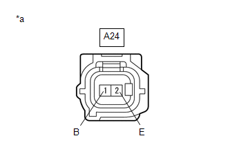
(b) Disconnect the A24 wireless door lock buzzer connector.
(c) Reconnect the 3F instrument panel junction block assembly connector.
(d) Measure the resistance according to the value(s) in the table below.
Standard Resistance:
|
Tester Connection |
Condition |
Specified Condition |
|---|---|---|
|
A24-1 (B) - MB-21 (BZR) |
Always |
Below 1 Ω |
|
A24-2 (E) - Body ground |
Always |
Below 1 Ω |
|
A24-1 (B) or MB-21 (BZR) - Body ground |
Always |
10 kΩ or higher |
| OK | |
REPLACE MAIN BODY ECU (MULTIPLEX NETWORK BODY ECU) |
|
|
8. |
CHECK HARNESS AND CONNECTOR (WIRELESS DOOR LOCK BUZZER - INSTRUMENT PANEL JUNCTION BLOCK ASSEMBLY) |
(a) Disconnect the 3F instrument panel junction block assembly connector.
(b) Disconnect the A24 wireless door lock buzzer connector.
(c) Measure the resistance according to the value(s) in the table below.
Standard Resistance:
|
Tester Connection |
Condition |
Specified Condition |
|---|---|---|
|
A24-1 (B) - 3F-29 |
Always |
Below 1 Ω |
|
A24-1 (B) or 3F-29 - Body ground |
Always |
10 kΩ or higher |
| OK | |
REPLACE INSTRUMENT PANEL JUNCTION BLOCK ASSEMBLY |
| NG | |
REPAIR OR REPLACE HARNESS OR CONNECTOR |
|
9. |
CHECK HAZARD WARNING LIGHTS OPERATION |
(a) Check that the hazard warning lights blink when the hazard warning signal switch is pressed.
OK:
Hazard warning lights blink.
| OK | |
REPLACE MAIN BODY ECU (MULTIPLEX NETWORK BODY ECU) |
| NG | |
GO TO LIGHTING SYSTEM (Proceed to Hazard Warning Switch Circuit) |
 Only Wireless Control Function is Inoperative
DESCRIPTION
The door control and tire pressure monitoring system receiver assembly receives
signals from the door control transmitter assembly and sends these signals to the
main body ECU (multip ...

Other materials:
Toyota CH-R Owners Manual > Adjusting the seats: Front seats
Adjustment procedure
Seat position adjustment lever
Seatback angle adjustment lever
Vertical height adjustment lever
Lumbar support adjustment switch (if equipped)
WARNING■When adjusting the seat position
Take care when adjusting the seat position to ensure that other pas ...
Toyota CH-R Service Manual > Front Seat Inner Belt Assembly: Inspection
INSPECTION
PROCEDURE
1. INSPECT FRONT SEAT INNER BELT ASSEMBLY (for Driver Side)
(a) w/o Occupant Classification System:
(1) Check the resistance.
Measure the resistance according to the value(s) in the table
below.
Standard Resistance:
...
Toyota C-HR (AX20) 2023-2026 Owner's Manual
Toyota CH-R Owners Manual
- For safety and security
- Instrument cluster
- Operation of each component
- Driving
- Interior features
- Maintenance and care
- When trouble arises
- Vehicle specifications
- For owners
Toyota CH-R Service Manual
- Introduction
- Maintenance
- Audio / Video
- Cellular Communication
- Navigation / Multi Info Display
- Park Assist / Monitoring
- Brake (front)
- Brake (rear)
- Brake Control / Dynamic Control Systems
- Brake System (other)
- Parking Brake
- Axle And Differential
- Drive Shaft / Propeller Shaft
- K114 Cvt
- 3zr-fae Battery / Charging
- Networking
- Power Distribution
- Power Assist Systems
- Steering Column
- Steering Gear / Linkage
- Alignment / Handling Diagnosis
- Front Suspension
- Rear Suspension
- Tire / Wheel
- Tire Pressure Monitoring
- Door / Hatch
- Exterior Panels / Trim
- Horn
- Lighting (ext)
- Mirror (ext)
- Window / Glass
- Wiper / Washer
- Door Lock
- Heating / Air Conditioning
- Interior Panels / Trim
- Lighting (int)
- Meter / Gauge / Display
- Mirror (int)
- Power Outlets (int)
- Pre-collision
- Seat
- Seat Belt
- Supplemental Restraint Systems
- Theft Deterrent / Keyless Entry

0.0091