Toyota CH-R Service Manual: Only Wireless Control Function is Inoperative
DESCRIPTION
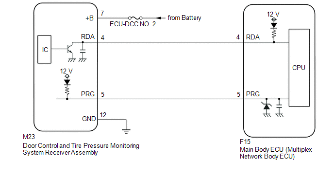
The door control and tire pressure monitoring system receiver assembly receives signals from the door control transmitter assembly and sends these signals to the main body ECU (multiplex network body ECU). The main body ECU (multiplex network body ECU) then controls all doors by sending lock/unlock signals to each door, and sends hazard flasher signals to the combination meter assembly.
WIRING DIAGRAM
CAUTION / NOTICE / HINT
NOTICE:
- Inspect the fuses for circuits related to this system before performing the following procedure.
- When replacing or inspecting the door control and tire pressure monitoring system receiver assembly and wire harness, do not change the position or length of the wire harness. If the wire harness is too close to the door control and tire pressure monitoring system receiver assembly, wireless function performance may be affected.
- When replacing the door control and tire pressure monitoring system receiver assembly, read the transmitter IDs stored in the old ECU using the Techstream and write them down before removal.
- It is necessary to perform initialization
.gif) after registration
of the transmitter IDs into the tire pressure warning ECU and receiver if
the ECU has been replaced.
after registration
of the transmitter IDs into the tire pressure warning ECU and receiver if
the ECU has been replaced.
PROCEDURE
|
1. |
CHECK POWER DOOR LOCK OPERATION |
(a) Check the power door lock operation.
Click here
OK:
Locked doors unlock
| NG | .gif) |
GO TO POWER DOOR LOCK CONTROL SYSTEM |
|
.gif)
|
2. |
CHECK KEY REMINDER WARNING SYSTEM |
(a) Check that the key reminder warning buzzer operates properly.
Click here
OK:
Key reminder warning buzzer operates properly.
| NG | |
GO TO KEY REMINDER WARNING SYSTEM |
|
|
3. |
CHECK DOOR CONTROL TRANSMITTER ASSEMBLY |
(a) When a known good registered door control transmitter assembly is used, check that the wireless functions operate properly.
|
Result |
Proceed to |
|---|---|
|
Wireless door lock/unlock function operates properly with a known good door control transmitter assembly. |
A |
|
Wireless door lock function does not operate. |
B |
| B | |
GO TO STEP 5 |
|
|
4. |
CHECK TRANSMITTER BATTERY (VOLTAGE) |
(a) Inspect the battery capacity.
(1) Remove the battery from the door control transmitter assembly that does not
operate (See page
). Attach a lead wire (0.6 mm (0.0236 in.) in diameter or less including wire sheath)
with tape or equivalent to the negative (-) terminal.
NOTICE:
Do not wrap the lead wire around a terminal, wedge it between the terminals, or solder it. A terminal may be deformed or damaged, and the battery will not be able to be installed correctly.
|
(b) Carefully pull the lead wire out from the position shown in the illustration and install the previously removed transmitter battery. NOTICE: When replacing the transmitter battery, before starting work, remove static electricity that has built up in the body by touching, for example, the vehicle to prevent the door control transmitter assembly from being damaged. |
|
.png)
|
(c) Check the transmitter battery voltage. HINT: Measure the transmitter battery voltage while pressing the lock or unlock switch on the door control transmitter assembly. Standard Voltage:
|
|
.png)
| OK | |
REPLACE DOOR CONTROL TRANSMITTER ASSEMBLY |
| NG | |
REPLACE TRANSMITTER BATTERY |
|
5. |
CHECK WAVE ENVIRONMENT |
(a) Bring the door control transmitter assembly near the door control and tire pressure monitoring system receiver assembly, and perform a wireless operation check.
HINT:
- When the door control transmitter assembly is brought near the door control and tire pressure monitoring system receiver assembly, the possibility of wave interference decreases, and it can be determined if wave interference is causing the problem symptom.
- If the inspection result is that the problem only occurs in certain locations or times of day, the possibility of wave interference is high. Also, added vehicle components may cause wave interference. If installed, remove them and perform the operation check.
OK:
Wireless functions operate properly.
| OK | |
END (AFFECTED BY WAVE INTERFERENCE) |
|
|
6. |
SWITCH TO SELF-DIAGNOSTIC MODE (USING TECHSTREAM) |
(a) Connect the Techstream to the DLC3.
(b) Turn the Ignition switch to ON.
(c) Turn the Techstream on.
(d) Enter the following menus: Body Electrical / Main Body / Wireless Diagnosis Mode.
Body Electrical > Main Body > Utility|
Tester Display |
|---|
|
Wireless Code Registration |
(e) Proceed to the next step in accordance with the prompts on the Techstream screen.
|
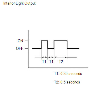
(f) Check that the system has switched to self-diagnostic mode by checking the interior light output pattern. |
|
|
|
7. |
CHECK SELF DIAGNOSTIC MODE |
(a) Inspect the diagnostic outputs when the door control transmitter assembly switch is pressed. The diagnostic outputs can be checked by the flash patterns of the interior lights.
.png)
|
Result |
Proceed to |
|---|---|
|
Normal wave (light flash pattern) is output. |
A |
|
Unmatching recognition code is output. |
B |
|
No diagnostic outputs. |
C |
| A | |
REPLACE MAIN BODY ECU (MULTIPLEX NETWORK BODY ECU)
|
| C | |
GO TO STEP 9 |
|
|
8. |
CHECK REGISTER RECOGNITION CODE |
(a) Check that the system can be switched to rewrite mode or add mode, and that a recognition code can be registered.
Click here
OK:
Recognition code can be registered.
| OK | |
END (GO TO OPERATION CHECK) |
| NG | |
GO TO STEP 13 |
|
9. |
CHECK DOOR CONTROL AND TIRE PRESSURE MONITORING SYSTEM RECEIVER ASSEMBLY (RESPONSE) |
(a) Prepare the door control transmitter assembly from another vehicle.
(b) Press and hold down the door control transmitter assembly switch.
(c) Check that an unmatching recognition code is output.
OK:
Unmatching recognition code is output.
| OK | |
REPLACE DOOR CONTROL (CUT KEY) TRANSMITTER ASSEMBLY |
|
|
10. |
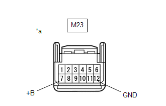
CHECK DOOR CONTROL AND TIRE PRESSURE MONITORING SYSTEM RECEIVER ASSEMBLY (+B, GND) |
|
(a) Disconnect the M23 door control and tire pressure monitoring system receiver assembly. |
|
(b) Measure the resistance according to the value(s) in the table below.
Standard Resistance:
|
Tester Connection |
Condition |
Specified Condition |
|---|---|---|
|
M23-12 (GND) - Body ground |
Always |
Below 1 Ω |
(c) Measure the voltage according to the value(s) in the table below.
Standard Voltage:
|
Tester Connection |
Condition |
Specified Condition |
|---|---|---|
|
M23-7 (+B) - Body ground |
Always |
11 to 14 V |
| NG | |
REPAIR OR REPLACE HARNESS OR CONNECTOR |
|
|
11. |
CHECK DOOR CONTROL AND TIRE PRESSURE MONITORING SYSTEM RECEIVER ASSEMBLY (OUTPUT) |
(a) Connect the M23 door control and tire pressure monitoring system receiver assembly.
|
(b) Measure the voltage according to the value(s) in the table below. Standard Voltage:
|
|
| NG | |
REPLACE DOOR CONTROL AND TIRE PRESSURE MONITORING SYSTEM RECEIVER ASSEMBLY
|
|
|
12. |
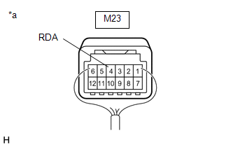
CHECK HARNESS AND CONNECTOR (MAIN BODY ECU (MULTIPLEX NETWORK BODY ECU) - DOOR CONTROL AND TIRE PRESSURE MONITORING SYSTEM RECEIVER ASSEMBLY) |
(a) Disconnect the F15 main body ECU (multiplex network body ECU) connector.
(b) Disconnect the M23 door control and tire pressure monitoring system receiver assembly connector.
(c) Measure the resistance according to the value(s) in the table below.
Standard Resistance:
|
Tester Connection |
Condition |
Specified Condition |
|---|---|---|
|
M23-4 (RDA) - F15-4 (RDA) |
Always |
Below 1 Ω |
|
M23-5 (PRG) - F15-5 (PRG) |
Always |
Below 1 Ω |
|
M23-4 (RDA) - Body ground |
Always |
10 kΩ or higher |
|
M23-5 (PRG) - Body ground |
Always |
10 kΩ or higher |
|
F15-4 (RDA) - Body ground |
Always |
10 kΩ or higher |
|
F15-5 (PRG) - Body ground |
Always |
10 kΩ or higher |
| NG | |
REPAIR OR REPLACE HARNESS OR CONNECTOR |
|
|
13. |
REPLACE DOOR CONTROL AND TIRE PRESSURE MONITORING SYSTEM RECEIVER ASSEMBLY |
(a) Temporarily replace the door control and tire pressure monitoring system receiver assembly with a new or known good one.
Click here
|
|
14. |
CHECK REGISTER RECOGNITION CODE |
(a) Perform the Registration procedure.
Click here
|
|
15. |
CHECK DOOR CONTROL AND TIRE PRESSURE MONITORING SYSTEM RECEIVER ASSEMBLY (OPERATION) |
(a) Check that the doors can be locked and unlocked by the door control transmitter assembly lock and unlock switches.
OK:
Doors can be locked and unlocked by the door control transmitter assembly.
| OK | |
END (DOOR CONTROL AND TIRE PRESSURE MONITORING SYSTEM RECEIVER ASSEMBLY WAS DEFECTIVE) |
| NG | |
REPLACE MAIN BODY ECU (MULTIPLEX NETWORK BODY ECU)
|
 Data List / Active Test
DATA LIST / ACTIVE TEST
DATA LIST
HINT:
Using the Techstream to read the Data List allows the values or states of switches,
sensors, actuators and other items to be read without removing any part ...
 No Answer-Back
DESCRIPTION
In some cases, wireless door lock control functions are normal but the hazard
warning light and wireless door lock buzzer answer-back functions*1 do not operate.
In such cases, hazard ...
Other materials:
Toyota CH-R Service Manual > Air Conditioning System(for Automatic Air Conditioning System With Side-mounted
Air Conditioner Pressure Sensor): Ambient Temperature Display System
DESCRIPTION
The thermistor assembly is installed in front of the cooler condenser assembly
to detect the ambient temperature which is used to control the air conditioning
system AUTO mode. This sensor is connected to the air conditioning amplifier assembly
and detects fluctuations in the ambi ...
Toyota CH-R Service Manual > Electric Parking Brake System: Electric Parking Brake AUTO Indicator Light Circuit
DESCRIPTION
Pulling the electric parking brake switch to the lock side for 5 seconds or more
changes the AUTO function (shift-linked function) to ON, and an AUTO Mode ON message
is displayed on the multi-information display in the combination meter.
Pressing the electric parking brake switch t ...
Toyota C-HR (AX20) 2023-2026 Owner's Manual
Toyota CH-R Owners Manual
- For safety and security
- Instrument cluster
- Operation of each component
- Driving
- Interior features
- Maintenance and care
- When trouble arises
- Vehicle specifications
- For owners
Toyota CH-R Service Manual
- Introduction
- Maintenance
- Audio / Video
- Cellular Communication
- Navigation / Multi Info Display
- Park Assist / Monitoring
- Brake (front)
- Brake (rear)
- Brake Control / Dynamic Control Systems
- Brake System (other)
- Parking Brake
- Axle And Differential
- Drive Shaft / Propeller Shaft
- K114 Cvt
- 3zr-fae Battery / Charging
- Networking
- Power Distribution
- Power Assist Systems
- Steering Column
- Steering Gear / Linkage
- Alignment / Handling Diagnosis
- Front Suspension
- Rear Suspension
- Tire / Wheel
- Tire Pressure Monitoring
- Door / Hatch
- Exterior Panels / Trim
- Horn
- Lighting (ext)
- Mirror (ext)
- Window / Glass
- Wiper / Washer
- Door Lock
- Heating / Air Conditioning
- Interior Panels / Trim
- Lighting (int)
- Meter / Gauge / Display
- Mirror (int)
- Power Outlets (int)
- Pre-collision
- Seat
- Seat Belt
- Supplemental Restraint Systems
- Theft Deterrent / Keyless Entry

0.0078