Toyota CH-R Service Manual: Only Back Door cannot be Opened
DESCRIPTION
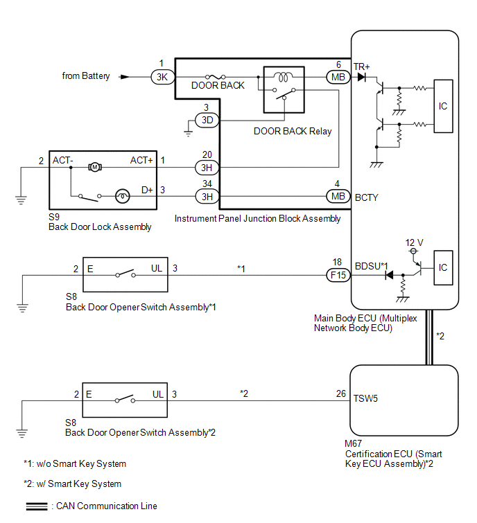
The main body ECU (multiplex network body ECU) receives signals from the back door opener switch assembly. When a signal received is the main body ECU (multiplex network body ECU) activates the back door lock motor.
WIRING DIAGRAM
CAUTION / NOTICE / HINT
NOTICE:
- Before replacing the main body ECU (multiplex network body ECU), refer
to Registration*.
Click here
.gif)
- *: w/ Smart Key System
- The power door lock control system uses the CAN communication system.
Inspect the communication function by following How to Proceed with Troubleshooting.
Troubleshoot the power door lock control system after confirming that the
communication systems are functioning properly.*
Click here
- *: w/ Smart Key System
- Before performing this troubleshooting procedure, perform troubleshooting
for the smart access system with push-button start (for Entry Function)
(Back Door Entry Unlock Function does not Operate) first.*
Click here
- *: w/ Smart Key System
PROCEDURE
|
1. |
CONFIRM MODEL |
(a) Choose the model to be inspected.
|
Result |
Proceed to |
|---|---|
|
w/ Smart Key System |
A |
|
w/o Smart Key System |
B |
| B | .gif) |
GO TO STEP 6 |
|
.gif)
|
2. |
INSPECT BACK DOOR LOCK ASSEMBLY |
(a) Remove the back door lock assembly.
Click here
(b) Inspect the back door lock assembly.
Click here
| NG | |
REPLACE BACK DOOR LOCK ASSEMBLY |
|
|
3. |
CHECK HARNESS AND CONNECTOR (BACK DOOR LOCK ASSEMBLY - INSTRUMENT PANEL JUNCTION BLOCK ASSEMBLY) |
(a) Disconnect the 3H instrument panel junction block assembly connector.
(b) Measure the resistance according to the value(s) in the table below.
Standard Resistance:
|
Tester Connection |
Condition |
Specified Condition |
|---|---|---|
|
S9-1 (ACT+) - 3H-20 |
Always |
Below 1 Ω |
|
S9-3 (D+) - 3H-34 |
Always |
Below 1 Ω |
|
S9-2 (ACT-) - Body ground |
Always |
Below 1 Ω |
|
S9-1 (ACT+) or 3H-20 - Body ground |
Always |
10 kΩ or higher |
|
S9-3 (D+) or 3H-34 - Body ground |
Always |
10 kΩ or higher |
| NG | |
REPAIR OR REPLACE HARNESS OR CONNECTOR |
|
|
4. |
INSPECT INSTRUMENT PANEL JUNCTION BLOCK ASSEMBLY |
(a) Remove the instrument panel junction block assembly.
Click here
|
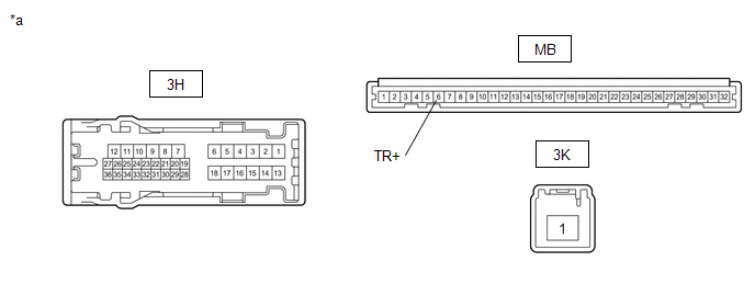
*a |
Component without harness connected (Instrument Panel Junction Block Assembly) |
- |
- |
(b) Remove the main body ECU (multiplex network body ECU) from the instrument panel junction block assembly.
(c) Measure the voltage according to the value(s) in the table below.
Standard Resistance:
|
Tester Connection |
Condition |
Specified Condition |
|---|---|---|
|
3H-20 - Body ground |
Battery voltage not applied between 3K-1 and MB-6 (TR+) |
Below 1 V |
|
3H-20 - Body ground |
Battery voltage applied between 3K-1 and MB-6 (TR+) |
11 to 14 V |
| NG | |
REPLACE INSTRUMENT PANEL JUNCTION BLOCK ASSEMBLY
|
|
|
5. |
CHECK BACK DOOR OPEN OPERATION |
(a) Check that the back door can be opened.
OK:
The back door can be opened.
| OK | |
END |
| NG | |
REPLACE MAIN BODY ECU (MULTIPLEX NETWORK BODY ECU)
|
|
6. |
CHECK POWER DOOR LOCK OPERATION (BASIC FUNCTION) |
(a) Check the power door lock basic function.
OK:
The power door lock basic functions operate normally.
| NG | |
GO TO PROBLEM SYMPTOMS TABLE
|
|
|
7. |
READ VALUE USING TECHSTREAM (Back Door Open) |
(a) Connect the Techstream to the DLC3.
(b) Turn the ignition switch to ON.
(c) Turn the Techstream on.
(d) Enter the following menus: Body Electrical / Main Body / Data List.
(e) Read the Data List according to the display on the Techstream.
Body Electrical > Main Body > Data List|
Tester Display |
Measurement Item |
Range |
Normal Condition |
Diagnostic Note |
|---|---|---|---|---|
|
Back Door Open |
Back door lock signal |
Prohibt or Permit |
Prohibt: Back door locked Permit: Back door unlocked |
- |
|
Tester Display |
|---|
|
Back Door Open |
OK:
On the Techstream screen, Prohibt or Permit is displayed accordingly.
| NG | |
REPLACE MAIN BODY ECU (MULTIPLEX NETWORK BODY ECU)
|
|
|
8. |
PERFORM ACTIVE TEST USING TECHSTREAM (Trunk and Back-Door Open) |
(a) Enter the following menus: Body Electrical / Main Body / Active Test.
(b) Perform the Active Test according to the display on the Techstream.
Body Electrical > Main Body > Active Test|
Tester Display |
Measurement Item |
Control Range |
Diagnostic Note |
|---|---|---|---|
|
Trunk and Back-Door Open |
Back door lock motor |
OFF/ON |
- |
|
Tester Display |
|---|
|
Trunk and Back-Door Open |
OK:
The back door lock assembly operates normally.
| NG | |
GO TO STEP 12 |
|
|
9. |
READ VALUE USING TECHSTREAM (Back Door Open Handle SW) |
(a) Enter the following menus: Body Electrical / Main Body / Data List.
(b) Read the Data List according to the display on the Techstream.
Body Electrical > Main Body > Data List|
Tester Display |
Measurement Item |
Range |
Normal Condition |
Diagnostic Note |
|---|---|---|---|---|
|
Back Door Open Handle SW |
Back door opener switch signal |
OFF or ON |
OFF: Back door closed ON: Back door open |
- |
|
Tester Display |
|---|
|
Back Door Open Handle SW |
OK:
On the Techstream screen, ON or OFF is displayed accordingly.
| OK | |
REPLACE MAIN BODY ECU (MULTIPLEX NETWORK BODY ECU)
|
|
|
10. |
INSPECT BACK DOOR OPENER SWITCH ASSEMBLY |
(a) Remove the back door opener switch assembly.
Click here
(b) Inspect the back door opener switch assembly.
Click here
| NG | |
REPLACE BACK DOOR OPENER SWITCH ASSEMBLY |
|
|
11. |
CHECK HARNESS AND CONNECTOR (BACK DOOR OPENER SWITCH ASSEMBLY - MAIN BODY ECU (MULTIPLEX NETWORK BODY ECU)) |
(a) Disconnect the F15 main body ECU (multiplex network body ECU) connector.
(b) Disconnect the S8 back door opener switch assembly connector.
(c) Measure the resistance according to the value(s) in the table below.
Standard Resistance:
|
Tester Connection |
Condition |
Specified Condition |
|---|---|---|
|
F15-18 (BDSU) - S8-3 (UL) |
Always |
Below 1 Ω |
|
S8-2 (E) - Body ground |
Always |
Below 1 Ω |
|
F15-18 (BDSU) or S8-3 (UL) - Body ground |
Always |
10 kΩ or higher |
| OK | |
REPLACE MAIN BODY ECU (MULTIPLEX NETWORK BODY ECU)
|
| NG | |
REPAIR OR REPLACE HARNESS OR CONNECTOR |
|
12. |
INSPECT BACK DOOR LOCK ASSEMBLY |
(a) Remove the back door lock assembly.
Click here
(b) Inspect the back door lock assembly.
Click here
| NG | |
REPLACE BACK DOOR LOCK ASSEMBLY |
|
|
13. |
CHECK HARNESS AND CONNECTOR (BACK DOOR LOCK ASSEMBLY - INSTRUMENT PANEL JUNCTION BLOCK ASSEMBLY) |
(a) Disconnect the 3H instrument panel junction block assembly connector.
(b) Disconnect the S9 back door lock assembly connector.
(c) Measure the resistance according to the value(s) in the table below.
Standard Resistance:
|
Tester Connection |
Condition |
Specified Condition |
|---|---|---|
|
S9-1 (ACT+) - 3H-20 |
Always |
Below 1 Ω |
|
S9-3 (D+) - 3H-34 |
Always |
Below 1 Ω |
|
S9-2 (ACT-) - Body ground |
Always |
Below 1 Ω |
|
S9-1 (ACT+) or 3H-20 - Body ground |
Always |
10 kΩ or higher |
|
S9-3 (D+) or 3H-34 - Body ground |
Always |
10 kΩ or higher |
| NG | |
REPAIR OR REPLACE HARNESS OR CONNECTOR |
|
|
14. |
INSPECT INSTRUMENT PANEL JUNCTION BLOCK ASSEMBLY |
(a) Remove the instrument panel junction block assembly.
Click here
|
*a |
Component without harness connected (Instrument Panel Junction Block Assembly) |
- |
- |
(b) Remove the main body ECU (multiplex network body ECU) from the instrument panel junction block assembly.
(c) Measure the resistance according to the value(s) in the table below.
Standard Resistance:
|
Tester Connection |
Condition |
Specified Condition |
|---|---|---|
|
3H-20 - Body ground |
Battery voltage not applied between 3K-1 and MB-6 (TR+) |
Below 1 V |
|
3H-20 - Body ground |
Battery voltage applied between 3K-1 and MB-6 (TR+) |
11 to 14 V |
| NG | |
REPLACE INSTRUMENT PANEL JUNCTION BLOCK ASSEMBLY
|
|
|
15. |
CHECK BACK DOOR OPEN OPERATION |
(a) Check that the back door can be opened.
OK:
The back door can be opened.
| OK | |
END |
| NG | |
REPLACE MAIN BODY ECU (MULTIPLEX NETWORK BODY ECU)
|
 Improper Operation
DESCRIPTION
In cases where doors locked (lock) by themselves even though a door lock operation
was not performed, possible causes include vehicle-side malfunction, environmental
malfunction, or o ...
 Rear Door Lock
...
Other materials:
Toyota CH-R Service Manual > Steering Wheel: Installation
INSTALLATION
CAUTION / NOTICE / HINT
NOTICE:
Do not replace the spiral cable with sensor sub-assembly with the battery
connected and the ignition switch ON.
Do not rotate the spiral cable with sensor sub-assembly without the
steering wheel assembly installed with the battery c ...
Toyota CH-R Service Manual > Electric Parking Brake System: Electric Parking Brake does not Operate
WIRING DIAGRAM
CAUTION / NOTICE / HINT
NOTICE:
Inspect the fuses for circuits related to this system before performing
the following inspection procedure.
The electric parking brake may still operate up to 20 seconds after
the ignition switch is turned off. Before disconnect ...
Toyota C-HR (AX20) 2023-2026 Owner's Manual
Toyota CH-R Owners Manual
- For safety and security
- Instrument cluster
- Operation of each component
- Driving
- Interior features
- Maintenance and care
- When trouble arises
- Vehicle specifications
- For owners
Toyota CH-R Service Manual
- Introduction
- Maintenance
- Audio / Video
- Cellular Communication
- Navigation / Multi Info Display
- Park Assist / Monitoring
- Brake (front)
- Brake (rear)
- Brake Control / Dynamic Control Systems
- Brake System (other)
- Parking Brake
- Axle And Differential
- Drive Shaft / Propeller Shaft
- K114 Cvt
- 3zr-fae Battery / Charging
- Networking
- Power Distribution
- Power Assist Systems
- Steering Column
- Steering Gear / Linkage
- Alignment / Handling Diagnosis
- Front Suspension
- Rear Suspension
- Tire / Wheel
- Tire Pressure Monitoring
- Door / Hatch
- Exterior Panels / Trim
- Horn
- Lighting (ext)
- Mirror (ext)
- Window / Glass
- Wiper / Washer
- Door Lock
- Heating / Air Conditioning
- Interior Panels / Trim
- Lighting (int)
- Meter / Gauge / Display
- Mirror (int)
- Power Outlets (int)
- Pre-collision
- Seat
- Seat Belt
- Supplemental Restraint Systems
- Theft Deterrent / Keyless Entry

0.0092