Toyota CH-R Service Manual: Light Sensor Circuit Malfunction (B1244)
DESCRIPTION
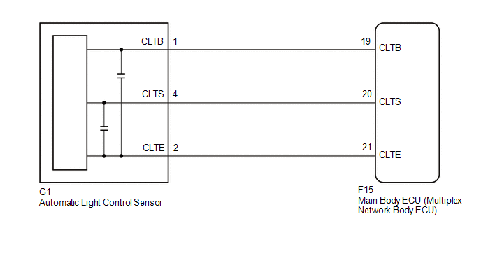
The automatic light control sensor detects ambient light. The sensor creates an electrical signal based on the amount of light detected, and sends the signal to the main body ECU (multiplex network body ECU). The main body ECU (multiplex network body ECU) turns on or off the headlights and taillights according to the signal.
|
DTC No. |
Detection Item |
DTC Detection Condition |
Trouble Area |
Note |
|---|---|---|---|---|
|
B1244 |
Light Sensor Circuit Malfunction |
Any of the following conditions is met:
|
|
- |
|
Vehicle Condition |
||||
|---|---|---|---|---|
|
Pattern 1 |
Pattern 2 |
Pattern 3 |
||
|
Diagnosis Condition |
Ignition switch ON |
○ |
○ |
○ |
|
Malfunction Status |
Malfunction in automatic light control sensor |
○ |
- |
- |
|
Open in automatic light control sensor circuit |
- |
○ |
- |
|
|
Short in automatic light control sensor circuit |
- |
- |
○ |
|
|
Detection Time |
- |
- |
- |
|
|
Number of Trips |
1 trip |
1 trip |
1 trip |
|
HINT:
DTC will be output when conditions for either of the patterns in the table above are met.
WIRING DIAGRAM
CAUTION / NOTICE / HINT
NOTICE:
Before replacing the main body ECU (multiplex network body ECU), refer to Registration.*1
Click here
.gif)
- *1: w/ Smart Key System
PROCEDURE
|
1. |
READ VALUE USING TECHSTREAM |
(a) Connect the Techstream to the DLC3.
(b) Turn the ignition switch to ON.
(c) Turn the Techstream on.
(d) Enter the following menus: Body Electrical / Main Body / Data List.
(e) Read the Data List according to the display on the Techstream.
Body Electrical > Main Body > Data List|
Tester Display |
Measurement Item |
Range |
Normal Condition |
Diagnostic Note |
|---|---|---|---|---|
|
Light Sensor Illuminance |
Light control sensor illuminance |
0 to 8191 lx |
Value is output according to ambient light level |
- |
|
Tester Display |
|---|
|
Light Sensor Illuminance |
OK:
Normal condition listed above is displayed.
| OK | .gif) |
REPLACE MAIN BODY ECU (MULTIPLEX NETWORK BODY ECU)
|
|
.gif)
|
2. |
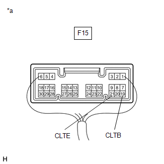
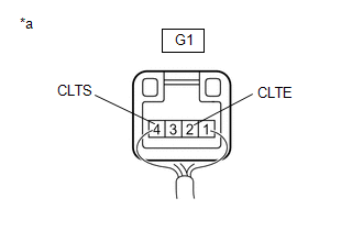
CHECK HARNESS AND CONNECTOR (MAIN BODY ECU (MULTIPLEX NETWORK BODY ECU) - AUTOMATIC LIGHT CONTROL SENSOR) |
(a) Disconnect the G1 automatic light control sensor connector.
(b) Disconnect the F15 main body ECU (multiplex network body ECU) connector.
(c) Measure the resistance according to the value(s) in the table below.
Standard Resistance:
|
Tester Connection |
Condition |
Specified Condition |
|---|---|---|
|
F15-21 (CLTE) - G1-2 (CLTE) |
Always |
Below 1 Ω |
|
F15-20 (CLTS) - G1-4 (CLTS) |
Always |
Below 1 Ω |
|
F15-19 (CLTB) - G1-1 (CLTB) |
Always |
Below 1 Ω |
|
F15-21 (CLTE) or G1-2 (CLTE) - Body ground |
Always |
10 kΩ or higher |
|
F15-20 (CLTS) or G1-4 (CLTS) - Body ground |
Always |
10 kΩ or higher |
|
F15-19 (CLTB) or G1-1 (CLTB) - Body ground |
Always |
10 kΩ or higher |
| NG | |
REPAIR OR REPLACE HARNESS OR CONNECTOR |
|
|
3. |
INSPECT MAIN BODY ECU (MULTIPLEX NETWORK BODY ECU) |
|
(a) Reconnect the F15 main body ECU (multiplex network body ECU) connector. |
|
(b) Measure the voltage according to the value(s) in the table below.
Standard Voltage:
|
Tester Connection |
Switch Condition |
Specified Condition |
|---|---|---|
|
F15-19 (CLTB) - F15-21 (CLTE) |
Ignition switch off |
Below 1 V |
|
Ignition switch ON |
11 to 14 V |
| NG | |
REPLACE MAIN BODY ECU (MULTIPLEX NETWORK BODY ECU)
|
|
|
4. |
INSPECT AUTOMATIC LIGHT CONTROL SENSOR |
|
(a) Reconnect the G1 automatic light control sensor connector. |
|
(b) Connect an oscilloscope to the automatic light control sensor connector.
|
(c) Check the waveform. OK:
HINT: The communication waveform changes according to the surrounding brightness. |
|
.png)
| OK | |
REPLACE MAIN BODY ECU (MULTIPLEX NETWORK BODY ECU)
|
| NG | |
REPLACE AUTOMATIC LIGHT CONTROL SENSOR |
 Diagnostic Trouble Code Chart
DIAGNOSTIC TROUBLE CODE CHART
Lighting System
DTC No.
Detection Item
Note
Link
B1244
Light Sensor Circuit Malfunction
...
 Left Headlight ECU Variation Error (B2456)
DESCRIPTION
This DTC is output when a headlight ECU sub-assembly LH that is incompatible
with the vehicle is installed.
The headlight ECU sub-assembly LH outputs DTC B2456.
DTC No.
...
Other materials:
Toyota CH-R Service Manual > Lighting (int): Luggage Compartment Room Light Bulb
Replacement
REPLACEMENT
PROCEDURE
1. REMOVE NO. 1 LUGGAGE COMPARTMENT LIGHT ASSEMBLY
Click here
2. REMOVE LUGGAGE COMPARTMENT LIGHT BULB
(a) Disengage the claws and guides to remove the luggage compartment light shade
as shown in the illustration.
Remove in this Di ...
Toyota CH-R Service Manual > Can Communication System: Check Bus 3 Line for Short to +B
DESCRIPTION
There may be a short circuit between one of the CAN bus lines and +B when no
resistance exists between terminal 6 (CA3H) of the central gateway ECU (network
gateway ECU) and terminal 16 (BAT) of the DLC3, or terminal 21 (CA3L) of the central
gateway ECU (network gateway ECU) and t ...
Toyota C-HR (AX20) 2023-2026 Owner's Manual
Toyota CH-R Owners Manual
- For safety and security
- Instrument cluster
- Operation of each component
- Driving
- Interior features
- Maintenance and care
- When trouble arises
- Vehicle specifications
- For owners
Toyota CH-R Service Manual
- Introduction
- Maintenance
- Audio / Video
- Cellular Communication
- Navigation / Multi Info Display
- Park Assist / Monitoring
- Brake (front)
- Brake (rear)
- Brake Control / Dynamic Control Systems
- Brake System (other)
- Parking Brake
- Axle And Differential
- Drive Shaft / Propeller Shaft
- K114 Cvt
- 3zr-fae Battery / Charging
- Networking
- Power Distribution
- Power Assist Systems
- Steering Column
- Steering Gear / Linkage
- Alignment / Handling Diagnosis
- Front Suspension
- Rear Suspension
- Tire / Wheel
- Tire Pressure Monitoring
- Door / Hatch
- Exterior Panels / Trim
- Horn
- Lighting (ext)
- Mirror (ext)
- Window / Glass
- Wiper / Washer
- Door Lock
- Heating / Air Conditioning
- Interior Panels / Trim
- Lighting (int)
- Meter / Gauge / Display
- Mirror (int)
- Power Outlets (int)
- Pre-collision
- Seat
- Seat Belt
- Supplemental Restraint Systems
- Theft Deterrent / Keyless Entry

0.0097