
Toyota CH-R Service Manual: Inspection
INSPECTION
PROCEDURE
1. INSPECT ELECTRICAL KEY TRANSMITTER SUB-ASSEMBLY
(a) Inspect the operation of the electrical key transmitter sub-assembly.
(1) Remove the transmitter battery from the electrical key transmitter sub-assembly.
Click here
.gif)
(2) Install a new or known good transmitter battery.
Click here
NOTICE:
When replacing the transmitter battery, before starting work, remove static electricity that has built up in the body by touching, for example, the vehicle to prevent the electrical key transmitter sub-assembly from being damaged.
HINT:
If a new or known good transmitter battery is not available, first connect 2 new 1.5 V batteries in series. Then connect leads to the batteries and apply 3 V to the electrical key transmitter sub-assembly, as shown in the illustration.
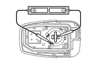
(3) From outside the vehicle, approximately 1 m (3.28 ft.) from the driver door outside door handle, test the electrical key transmitter sub-assembly by pointing its key plate at the vehicle and pressing an electrical key transmitter sub-assembly switch.
OK:
The door lock can be operated via the electrical key transmitter sub-assembly.
The LED comes on more than once.
- The operational area differs depending on the user, the way the electrical key transmitter sub-assembly is held, and the location.
- The weak radio waves of the electrical key transmitter sub-assembly may be affected if the area has strong radio waves or noise. The electrical key transmitter sub-assembly operation area may be shortened or the electrical key transmitter sub-assembly may not function.
(b) Inspect the transmitter battery capacity.
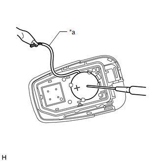
(1) Remove the transmitter battery from the electrical key transmitter sub-assembly that does not operate. Attach a lead wire (0.6 mm (0.0236 in.) in diameter or less including wire sheath) with tape or equivalent to the negative terminal.
Click here
NOTICE:
Do not wrap the lead wire around a terminal, wedge it between the terminals, or solder it. A terminal may be deformed or damaged, and the transmitter battery will not be able to be installed correctly.
|
(2) Carefully pull the lead wire out from the position shown in the illustration and install the previously removed transmitter battery. NOTICE: When replacing the transmitter battery, before starting work, remove static electricity that has built up in the body by touching, for example, the vehicle to prevent the electrical key transmitter sub-assembly from being damaged. |
|
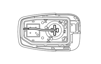
|
(3) Check the transmitter battery voltage. HINT:
Standard Voltage:
If the result is not as specified, replace the transmitter battery. |
|
 Removal
REMOVAL
CAUTION / NOTICE / HINT
NOTICE:
Take extra care when handling these precision electronic components.
PROCEDURE
1. REMOVE TRANSMITTER BATTERY
(a) Slide the release hook knob to remove the ...
 Installation
INSTALLATION
CAUTION / NOTICE / HINT
NOTICE:
Take extra care when handling these precision electronic components.
PROCEDURE
1. INSTALL TRANSMITTER BATTERY
(a) Install a new transmitter battery w ...
Other materials:
Toyota CH-R Service Manual > Audio And Visual System(for Radio And Display Type): Terminals Of Ecu
TERMINALS OF ECU
RADIO AND DISPLAY RECEIVER ASSEMBLY
*A
w/ Navigation System
*B
w/ Manual (SOS) Switch
*C
w/o Navigation System
*D
for Satellite Radio
Terminal No. (Symbol)
...
Toyota CH-R Service Manual > Pre-collision System: Operation Check
OPERATION CHECK
CHECK PRE-COLLISION SYSTEM SETTING
(a) Turn the ignition switch to ON.
(b) Operate the steering pad switch assembly to change the setting of PCS on
the multi-information display to "On" and check that the pre-collision system turns
on.
HINT:
When the ignition switc ...
Toyota C-HR (AX20) 2023-2026 Owner's Manual
Toyota CH-R Owners Manual
- For safety and security
- Instrument cluster
- Operation of each component
- Driving
- Interior features
- Maintenance and care
- When trouble arises
- Vehicle specifications
- For owners
Toyota CH-R Service Manual
- Introduction
- Maintenance
- Audio / Video
- Cellular Communication
- Navigation / Multi Info Display
- Park Assist / Monitoring
- Brake (front)
- Brake (rear)
- Brake Control / Dynamic Control Systems
- Brake System (other)
- Parking Brake
- Axle And Differential
- Drive Shaft / Propeller Shaft
- K114 Cvt
- 3zr-fae Battery / Charging
- Networking
- Power Distribution
- Power Assist Systems
- Steering Column
- Steering Gear / Linkage
- Alignment / Handling Diagnosis
- Front Suspension
- Rear Suspension
- Tire / Wheel
- Tire Pressure Monitoring
- Door / Hatch
- Exterior Panels / Trim
- Horn
- Lighting (ext)
- Mirror (ext)
- Window / Glass
- Wiper / Washer
- Door Lock
- Heating / Air Conditioning
- Interior Panels / Trim
- Lighting (int)
- Meter / Gauge / Display
- Mirror (int)
- Power Outlets (int)
- Pre-collision
- Seat
- Seat Belt
- Supplemental Restraint Systems
- Theft Deterrent / Keyless Entry

0.0102