Toyota CH-R Service Manual: Driver Side Power Window does not Operate with Power Window Master Switch
DESCRIPTION
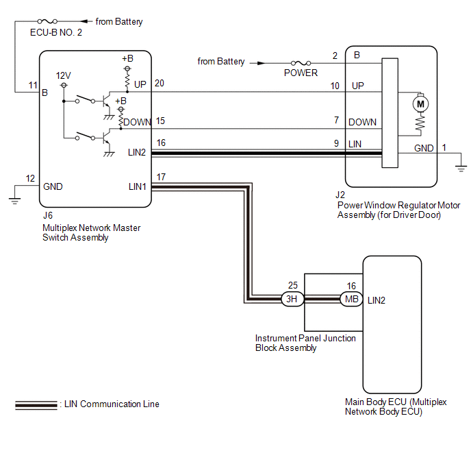
When the ignition switch is ON, the power window regulator motor assembly (for driver door) is operated by the multiplex network master switch assembly. The power window regulator motor assembly (for driver door) has motor, regulator and ECU functions.
WIRING DIAGRAM
CAUTION / NOTICE / HINT
NOTICE:
- The power window control system uses the LIN communication system. Inspect
the communication function by following How to Proceed with Troubleshooting.
Troubleshoot the power window control system after confirming that the communication
system is functioning properly.
Click here
.gif)
- If the power window regulator motor assembly (for driver door) has been
replaced with a new one, initialize the power window control system.
Click here
- Inspect the fuses for circuits related to this system before performing the following procedure.
- If the main body ECU (multiplex network body ECU) is replaced, refer
to Registration.*1
Click here
- *1: w/ Smart Key System
PROCEDURE
|
1. |
READ VALUE USING TECHSTREAM (MAIN BODY) |
(a) Connect the Techstream to the DLC3.
(b) Turn the ignition switch to ON.
(c) Turn the Techstream on.
(d) Enter the following menus: Body Electrical / Main Body / Data List.
(e) Read the Data List according to the display on the Techstream.
Body Electrical > Main Body > Data List|
Tester Display |
Measurement Item |
Range |
Normal Condition |
Diagnostic Note |
|---|---|---|---|---|
|
Communication D-Door Motor |
Connection status between power window regulator motor assembly (for driver door) and main body ECU (multiplex network body ECU) |
STOP or OK |
STOP: Communication stopped OK: Normal communication |
- |
|
Communication Master SW |
Connection status between multiplex network master switch assembly and main body ECU (multiplex network body ECU) |
STOP or OK |
STOP: Communication stopped OK: Normal communication |
- |
|
Tester Display |
|---|
|
Communication D-Door Motor |
|
Communication Master SW |
OK:
OK is displayed for each Data List item above.
| NG | .gif) |
GO TO LIN COMMUNICATION SYSTEM (Proceed to How to Proceed with Troubleshooting) |
|
.gif)
|
2. |
READ VALUE USING TECHSTREAM (D-DOOR MOTOR) |
(a) Enter the following menus: Body Electrical / D-Door Motor / Data List.
(b) Read the Data List according to the display on the Techstream.
Body Electrical > D-Door Motor > Data List|
Tester Display |
Measurement Item |
Range |
Normal Condition |
Diagnostic Note |
|---|---|---|---|---|
|
D Door P/W Up SW |
Driver door power window manual up switch signal |
OFF or ON |
OFF: Driver door power window manual up switch not being operated ON: Driver door power window manual up switch being operated |
- |
|
D Door P/W Down SW |
Driver door power window manual down switch signal |
OFF or ON |
OFF: Driver door power window manual down switch not being operated ON: Driver door power window manual down switch being operated |
- |
|
Tester Display |
|---|
|
D Door P/W Up SW |
|
D Door P/W Down SW |
OK:
On the Techstream screen, ON or OFF is displayed accordingly.
| NG | |
GO TO STEP 4 |
|
|
3. |
PERFORM ACTIVE TEST USING TECHSTREAM (D-DOOR MOTOR) |
(a) Enter the following menus: Body Electrical / D-Door Motor / Active Test.
(b) Perform the Active Test according to the display on the Techstream.
CAUTION:
Be careful to avoid injuries as this test causes vehicle parts to move. During the Active Test, the jam protection function will not operate.
Body Electrical > D-Door Motor > Active Test|
Tester Display |
Measurement Item |
Control Range |
Diagnostic Note |
|---|---|---|---|
|
Power Window |
Power window |
OFF / DOWN / UP |
- |
|
Tester Display |
|---|
|
Power Window |
OK:
Driver door power window operates normally.
| OK | |
REPLACE MAIN BODY ECU (MULTIPLEX NETWORK BODY ECU)
|
| NG | |
REPLACE POWER WINDOW REGULATOR MOTOR ASSEMBLY (FOR DRIVER DOOR) |
|
4. |
CHECK HARNESS AND CONNECTOR (MULTIPLEX NETWORK MASTER SWITCH ASSEMBLY - POWER WINDOW REGULATOR MOTOR ASSEMBLY (FOR DRIVER DOOR)) |
(a) Disconnect the J6 multiplex network master switch assembly connector.
(b) Measure the resistance according to the value(s) in the table below.
(c) Measure the resistance according to the value(s) in the table below.
Standard Resistance:
|
Tester Connection |
Condition |
Specified Condition |
|---|---|---|
|
J6-20 (UP) - J2-10 (UP) |
Always |
Below 1 Ω |
|
J6-20 (UP) or J2-10 (UP) - Body ground |
Always |
10 kΩ or higher |
|
J6-15 (DOWN) - J2-7 (DOWN) |
Always |
Below 1 Ω |
|
J6-15 (DOWN) or J2-7 (DOWN) - Body ground |
Always |
10 kΩ or higher |
| NG | |
REPAIR OR REPLACE HARNESS OR CONNECTOR |
|
|
5. |
REPLACE MULTIPLEX NETWORK MASTER SWITCH ASSEMBLY |
(a) Replace the multiplex network master switch assembly.
Click here
|
|
6. |
CHECK MANUAL UP / DOWN FUNCTION (FOR DRIVER DOOR) |
(a) Check that the driver door power window moves when the manual up and down functions of the multiplex network master switch assembly are operated.
Click here
OK:
Driver door manual up and down functions are normal.
| OK | |
END (MULTIPLEX NETWORK MASTER SWITCH ASSEMBLY WAS DEFECTIVE) |
| NG | |
REPLACE POWER WINDOW REGULATOR MOTOR ASSEMBLY (FOR DRIVER DOOR) |
 Remote Up / Down Function does not Operate
DESCRIPTION
When the ignition switch is ON, the multiplex network master switch assembly
sends remote up and down signals to each power window regulator motor assembly via
LIN communication.
WIR ...
 Front Passenger Side Power Window does not Operate with Front Passenger Side
Power Window Switch
Front Passenger Side Power Window does not Operate with Front Passenger Side
Power Window Switch
DESCRIPTION
When the ignition switch is ON, the power window regulator motor assembly (for
front passenger door) is operated by the power window regulator switch assembly.
The power window regula ...
Other materials:
Toyota CH-R Service Manual > Back Door: Components
COMPONENTS
ILLUSTRATION
*A
w/ Package Tray Trim
*B
w/ Tonneau Cover
*1
PACKAGE TRAY TRIM PANEL ASSEMBLY
*2
TONNEAU COVER ASSEMBLY
ILLUSTRATION
*1
BACK DOOR LOCK ASSEMB ...
Toyota CH-R Service Manual > Oil Pressure Sensor: Removal
REMOVAL
CAUTION / NOTICE / HINT
The necessary procedures (adjustment, calibration, initialization, or registration)
that must be performed after parts are removed, installed, or replaced during the
oil pressure sensor removal/installation are shown below.
Necessary Procedure After Parts Remov ...
Toyota C-HR (AX20) 2023-2026 Owner's Manual
Toyota CH-R Owners Manual
- For safety and security
- Instrument cluster
- Operation of each component
- Driving
- Interior features
- Maintenance and care
- When trouble arises
- Vehicle specifications
- For owners
Toyota CH-R Service Manual
- Introduction
- Maintenance
- Audio / Video
- Cellular Communication
- Navigation / Multi Info Display
- Park Assist / Monitoring
- Brake (front)
- Brake (rear)
- Brake Control / Dynamic Control Systems
- Brake System (other)
- Parking Brake
- Axle And Differential
- Drive Shaft / Propeller Shaft
- K114 Cvt
- 3zr-fae Battery / Charging
- Networking
- Power Distribution
- Power Assist Systems
- Steering Column
- Steering Gear / Linkage
- Alignment / Handling Diagnosis
- Front Suspension
- Rear Suspension
- Tire / Wheel
- Tire Pressure Monitoring
- Door / Hatch
- Exterior Panels / Trim
- Horn
- Lighting (ext)
- Mirror (ext)
- Window / Glass
- Wiper / Washer
- Door Lock
- Heating / Air Conditioning
- Interior Panels / Trim
- Lighting (int)
- Meter / Gauge / Display
- Mirror (int)
- Power Outlets (int)
- Pre-collision
- Seat
- Seat Belt
- Supplemental Restraint Systems
- Theft Deterrent / Keyless Entry

0.0125