Toyota CH-R Service Manual: System Diagram
SYSTEM DIAGRAM
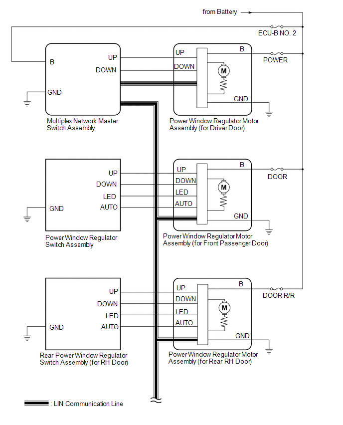
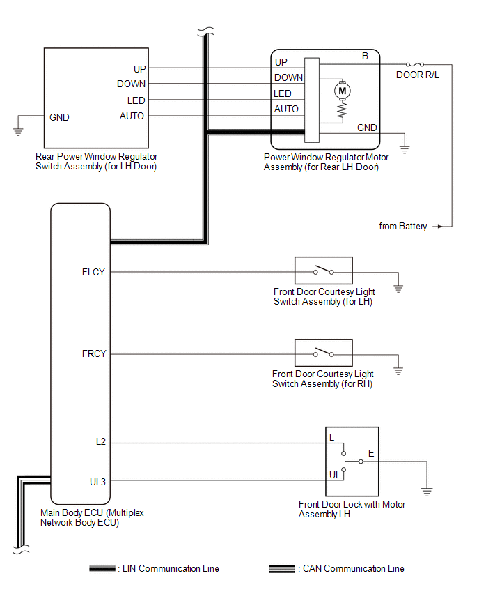
Power Window Control System
 Communication Table
|
Transmitting ECU |
Receiving ECU |
Signal |
Communication Method |
|---|---|---|---|
|
Multiplex Network Master Switch Assembly |
Power Window Regulator Motor Assembly (for Driver Door) |
Power window auto up and down signal |
LIN |
|
Power window remote up and down signal |
LIN |
|
|
Main Body ECU (Multiplex Network Body ECU) |
|
Power window operation permission signal |
LIN |
|
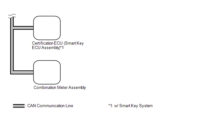
Certification ECU (Smart Key ECU Assembly)*1 |
Main Body ECU (Multiplex Network Body ECU) |
Wireless power window operation signal |
CAN |
|
Main Body ECU (Multiplex Network Body ECU) |
Combination Meter Assembly |
Window open warning request signal |
CAN |
- *1: w/ Smart Key System
 Parts Location
PARTS LOCATION
ILLUSTRATION
*A
w/ Smart Key System
-
-
*1
MAIN BODY ECU (MULTIPLEX NETWORK BODY ECU)
*2
...
 System Description
SYSTEM DESCRIPTION
POWER WINDOW CONTROL SYSTEM DESCRIPTION
(a) The power window control system controls the power window operation using
the power window regulator motor assemblies. The main contr ...
Other materials:
Toyota CH-R Service Manual > Occupant Detection Sensor: Inspection
INSPECTION
PROCEDURE
1. INSPECT OCCUPANT DETECTION SENSOR (SEPARATE TYPE FRONT SEAT CUSHION PAD)
(a) Check the resistance.
(1) Measure the resistance according to the value(s) in the table below.
Standard Resistance:
Tester Connection
Condition ...
Toyota CH-R Service Manual > Continuously Variable Transaxle Assembly(when Not Using The Engine Support Bridge): Installation
INSTALLATION
CAUTION / NOTICE / HINT
CAUTION:
The engine assembly with continuously variable transaxle assembly is very heavy.
Be sure to follow the procedure described in the repair manual, or the engine lifter
may suddenly drop.
PROCEDURE
1. INSTALL TRANSMISSION BREATHER HOSE SUB-ASSEMBLY ...
Toyota C-HR (AX20) 2023-2026 Owner's Manual
Toyota CH-R Owners Manual
- For safety and security
- Instrument cluster
- Operation of each component
- Driving
- Interior features
- Maintenance and care
- When trouble arises
- Vehicle specifications
- For owners
Toyota CH-R Service Manual
- Introduction
- Maintenance
- Audio / Video
- Cellular Communication
- Navigation / Multi Info Display
- Park Assist / Monitoring
- Brake (front)
- Brake (rear)
- Brake Control / Dynamic Control Systems
- Brake System (other)
- Parking Brake
- Axle And Differential
- Drive Shaft / Propeller Shaft
- K114 Cvt
- 3zr-fae Battery / Charging
- Networking
- Power Distribution
- Power Assist Systems
- Steering Column
- Steering Gear / Linkage
- Alignment / Handling Diagnosis
- Front Suspension
- Rear Suspension
- Tire / Wheel
- Tire Pressure Monitoring
- Door / Hatch
- Exterior Panels / Trim
- Horn
- Lighting (ext)
- Mirror (ext)
- Window / Glass
- Wiper / Washer
- Door Lock
- Heating / Air Conditioning
- Interior Panels / Trim
- Lighting (int)
- Meter / Gauge / Display
- Mirror (int)
- Power Outlets (int)
- Pre-collision
- Seat
- Seat Belt
- Supplemental Restraint Systems
- Theft Deterrent / Keyless Entry

0.0089