Toyota CH-R Service Manual: Parts Location
PARTS LOCATION
ILLUSTRATION
|
*A |
w/ Retract Mirror |
- |
- |
|
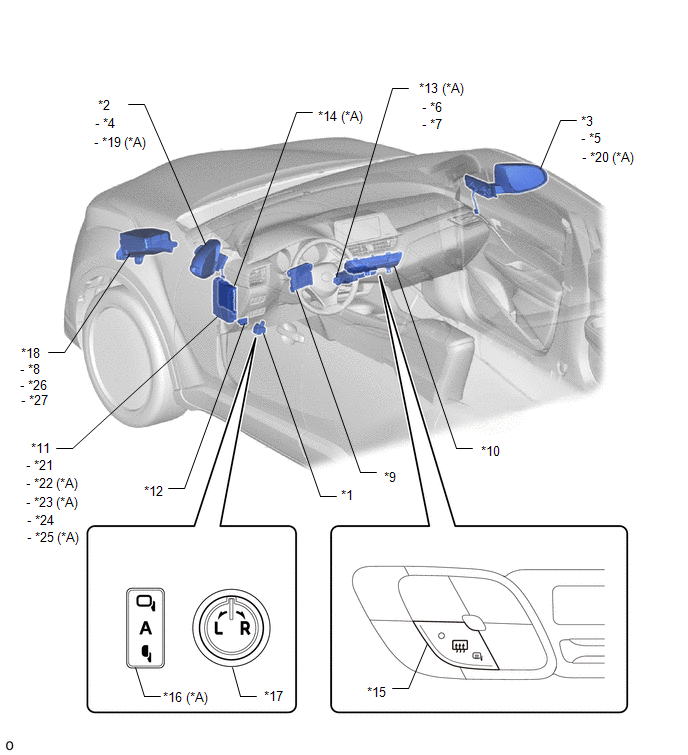
*1 |
OUTER MIRROR SWITCH ASSEMBLY |
*2 |
OUTER REAR VIEW MIRROR ASSEMBLY LH |
|
*3 |
OUTER REAR VIEW MIRROR ASSEMBLY RH |
*4 |
OUTER MIRROR LH |
|
*5 |
OUTER MIRROR RH |
*6 |
MIRROR(+) RELAY |
|
*7 |
MIRROR(-) RELAY |
*8 |
DEF RELAY |
|
*9 |
AIR CONDITIONING AMPLIFIER ASSEMBLY |
*10 |
AIR CONDITIONING CONTROL ASSEMBLY |
|
*11 |
INSTRUMENT PANEL JUNCTION BLOCK ASSEMBLY |
*12 |
DLC3 |
|
*13 |
NO. 4 RELAY BLOCK ASSEMBLY |
*14 |
MAIN BODY ECU (MULTIPLEX NETWORK BODY ECU) |
|
*15 |
MIRROR HEATER SWITCH (REAR WINDOW DEFOGGER SWITCH) |
*16 |
MIRROR RETRACT SWITCH |
|
*17 |
MIRROR SELECT AND SURFACE ADJUST SWITCH |
*18 |
NO. 1 ENGINE ROOM RELAY BLOCK |
|
*19 |
OUTER MIRROR RETRACTOR LH |
*20 |
OUTER MIRROR RETRACTOR RH |
|
*21 |
ECU-ACC FUSE |
*22 |
ECU-B NO. 2 FUSE |
|
*23 |
ECU-DCC NO. 2 FUSE |
*24 |
ECU-IG1 NO. 3 FUSE |
|
*25 |
ECU-IG1 NO. 4 FUSE |
*26 |
DEF FUSE |
|
*27 |
MIR HTR FUSE |
- |
- |
 Precaution
PRECAUTION
IGNITION SWITCH EXPRESSIONS
(a) The type of ignition switch used on this model differs depending on the specifications
of the vehicle. The expressions listed in the table below are used ...
 System Diagram
SYSTEM DIAGRAM
ELECTRICAL REMOTE CONTROL MIRROR FUNCTION (w/o Retract Mirror)
ELECTRICAL REMOTE CONTROL MIRROR FUNCTION (w/ Retract Mirror)
MIRROR HEATER FUNCTION
Communication Table
...
Other materials:
Toyota CH-R Service Manual > Lighting System: Light Sensor Circuit Malfunction (B1244)
DESCRIPTION
The automatic light control sensor detects ambient light. The sensor creates
an electrical signal based on the amount of light detected, and sends the signal
to the main body ECU (multiplex network body ECU). The main body ECU (multiplex
network body ECU) turns on or off the headl ...
Toyota CH-R Service Manual > Lighting (ext): License Plate Light Assembly
Components
COMPONENTS
ILLUSTRATION
*1
LICENSE PLATE LIGHT ASSEMBLY
-
-
Removal
REMOVAL
CAUTION / NOTICE / HINT
HINT:
Use the same procedure for the RH side and LH side.
The following procedure is for the LH side.
P ...
Toyota C-HR (AX20) 2023-2026 Owner's Manual
Toyota CH-R Owners Manual
- For safety and security
- Instrument cluster
- Operation of each component
- Driving
- Interior features
- Maintenance and care
- When trouble arises
- Vehicle specifications
- For owners
Toyota CH-R Service Manual
- Introduction
- Maintenance
- Audio / Video
- Cellular Communication
- Navigation / Multi Info Display
- Park Assist / Monitoring
- Brake (front)
- Brake (rear)
- Brake Control / Dynamic Control Systems
- Brake System (other)
- Parking Brake
- Axle And Differential
- Drive Shaft / Propeller Shaft
- K114 Cvt
- 3zr-fae Battery / Charging
- Networking
- Power Distribution
- Power Assist Systems
- Steering Column
- Steering Gear / Linkage
- Alignment / Handling Diagnosis
- Front Suspension
- Rear Suspension
- Tire / Wheel
- Tire Pressure Monitoring
- Door / Hatch
- Exterior Panels / Trim
- Horn
- Lighting (ext)
- Mirror (ext)
- Window / Glass
- Wiper / Washer
- Door Lock
- Heating / Air Conditioning
- Interior Panels / Trim
- Lighting (int)
- Meter / Gauge / Display
- Mirror (int)
- Power Outlets (int)
- Pre-collision
- Seat
- Seat Belt
- Supplemental Restraint Systems
- Theft Deterrent / Keyless Entry

0.0086