Toyota CH-R Service Manual: Inspection
INSPECTION
PROCEDURE
1. INSPECT OUTER MIRROR SWITCH ASSEMBLY (w/o Retract Mirror)
(a) Check the mirror select and surface adjust switch.
|
(1) Turn the mirror select and surface adjust switch to the L position. |
|
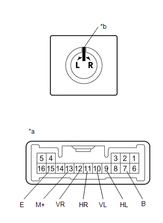
(2) Measure the resistance according to the value(s) in the table below.
Standard Resistance (for left side):
|
Tester Connection |
Condition |
Specified Condition |
|---|---|---|
|
10 (VL) - 7 (B) 13 (M+) - 15 (E) |
Up |
Below 1 Ω |
|
Off |
10 kΩ or higher |
|
|
10 (VL) - 15 (E) 13 (M+) - 7 (B) |
Down |
Below 1 Ω |
|
Off |
10 kΩ or higher |
|
|
9 (HL) - 7 (B) 13 (M+) - 15 (E) |
Left |
Below 1 Ω |
|
Off |
10 kΩ or higher |
|
|
9 (HL) - 15 (E) 13 (M+) - 7 (B) |
Right |
Below 1 Ω |
|
Off |
10 kΩ or higher |
(3) Turn the mirror select and surface adjust switch to the R position.
(4) Measure the resistance according to the value(s) in the table below.
Standard Resistance (for right side):
|
Tester Connection |
Condition |
Specified Condition |
|---|---|---|
|
12 (VR) - 7 (B) 13 (M+) - 15 (E) |
Up |
Below 1 Ω |
|
Off |
10 kΩ or higher |
|
|
12 (VR) - 15 (E) 13 (M+) - 7 (B) |
Down |
Below 1 Ω |
|
Off |
10 kΩ or higher |
|
|
11 (HR) - 7 (B) 13 (M+) - 15 (E) |
Left |
Below 1 Ω |
|
Off |
10 kΩ or higher |
|
|
11 (HR) - 15 (E) 13 (M+) - 7 (B) |
Right |
Below 1 Ω |
|
Off |
10 kΩ or higher |
If the result is not as specified, replace the outer mirror switch assembly.
|
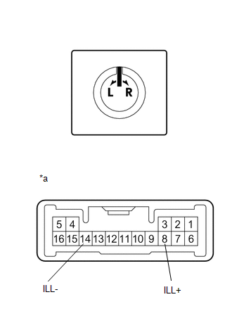
(b) Check that the LED illuminates. (1) Apply battery voltage to the outer mirror switch assembly and check that the LED illuminates. OK:
If the result is not as specified, replace the outer mirror switch assembly. |
|
2. INSPECT OUTER MIRROR SWITCH ASSEMBLY (w/ Retract Mirror)
(a) Check the mirror select and surface adjust switch.
|
(1) Turn the mirror select and surface adjust switch to the L position. |
|
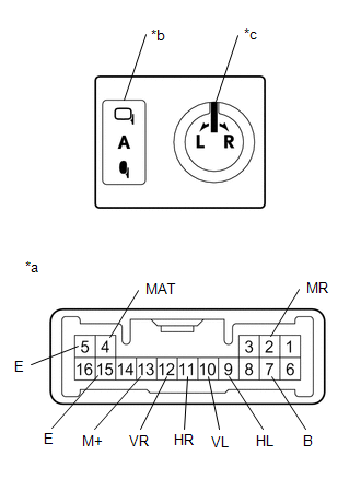
(2) Measure the resistance according to the value(s) in the table below.
Standard Resistance (for left side):
|
Tester Connection |
Condition |
Specified Condition |
|---|---|---|
|
10 (VL) - 7 (B) 13 (M+) - 15 (E) |
Up |
Below 1 Ω |
|
Off |
10 kΩ or higher |
|
|
10 (VL) - 15 (E) 13 (M+) - 7 (B) |
Down |
Below 1 Ω |
|
Off |
10 kΩ or higher |
|
|
9 (HL) - 7 (B) 13 (M+) - 15 (E) |
Left |
Below 1 Ω |
|
Off |
10 kΩ or higher |
|
|
9 (HL) - 15 (E) 13 (M+) - 7 (B) |
Right |
Below 1 Ω |
|
Off |
10 kΩ or higher |
(3) Turn the mirror select and surface adjust switch to the R position.
(4) Measure the resistance according to the value(s) in the table below.
Standard Resistance (for right side):
|
Tester Connection |
Condition |
Specified Condition |
|---|---|---|
|
12 (VR) - 7 (B) 13 (M+) - 15 (E) |
Up |
Below 1 Ω |
|
Off |
10 kΩ or higher |
|
|
12 (VR) - 15 (E) 13 (M+) - 7 (B) |
Down |
Below 1 Ω |
|
Off |
10 kΩ or higher |
|
|
11 (HR) - 7 (B) 13 (M+) - 15 (E) |
Left |
Below 1 Ω |
|
Off |
10 kΩ or higher |
|
|
11 (HR) - 15 (E) 13 (M+) - 7 (B) |
Right |
Below 1 Ω |
|
Off |
10 kΩ or higher |
(5) Check the mirror retract switch.
(6) Measure the resistance according to the value(s) in the table below.
Standard Resistance:
|
Tester Connection |
Condition |
Specified Condition |
|---|---|---|
|
4 (MAT) - 5 (E) |
AUTO position |
Below 1 Ω |
|
Except AUTO position |
10 kΩ or higher |
|
|
2 (MR) - 5 (E) |
Retract position |
Below 1 Ω |
|
Except retract position |
10 kΩ or higher |
If the result is not as specified, replace the outer mirror switch assembly.
|
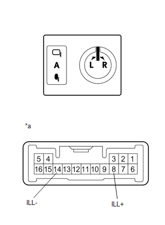
(b) Check that the LED illuminates. (1) Apply battery voltage to the outer mirror switch assembly and check that the LED illuminates. OK:
If the result is not as specified, replace the outer mirror switch assembly. |
|
 Removal
REMOVAL
PROCEDURE
1. REMOVE MULTIPLEX NETWORK MASTER SWITCH ASSEMBLY WITH FRONT ARMREST BASE UPPER
PANEL
Click here
2. REMOVE OUTER MIRROR SWITCH ASSEMBLY
(a) Using a screwdriv ...
 Installation
INSTALLATION
PROCEDURE
1. INSTALL OUTER MIRROR SWITCH ASSEMBLY
(a) Engage the claws to install the outer mirror switch assembly.
2. INSTA ...
Other materials:
Toyota CH-R Owners Manual > Adjusting the steering wheel and mirrors: Inside rear view mirror
The rear view mirror's position can be adjusted to enable sufficient
confirmation of the rear view.
Adjusting the height of rear view mirror
The height of the rear view mirror can be adjusted to suit your driving posture.
Adjust the height of the rear view mirror by moving it up and down.
...
Toyota CH-R Service Manual > Brake Master Cylinder: Reassembly
REASSEMBLY
PROCEDURE
1. INSTALL BRAKE MASTER CYLINDER RESERVOIR STRAINER
(a) Install the brake master cylinder reservoir strainer to the brake master
cylinder reservoir assembly.
2. INSTALL BRAKE MASTER CYLINDER RESERVOIR FILLER CAP ASSEMBLY
(a) Install the brake master cylinder reservoir fil ...
Toyota C-HR (AX20) 2023-2026 Owner's Manual
Toyota CH-R Owners Manual
- For safety and security
- Instrument cluster
- Operation of each component
- Driving
- Interior features
- Maintenance and care
- When trouble arises
- Vehicle specifications
- For owners
Toyota CH-R Service Manual
- Introduction
- Maintenance
- Audio / Video
- Cellular Communication
- Navigation / Multi Info Display
- Park Assist / Monitoring
- Brake (front)
- Brake (rear)
- Brake Control / Dynamic Control Systems
- Brake System (other)
- Parking Brake
- Axle And Differential
- Drive Shaft / Propeller Shaft
- K114 Cvt
- 3zr-fae Battery / Charging
- Networking
- Power Distribution
- Power Assist Systems
- Steering Column
- Steering Gear / Linkage
- Alignment / Handling Diagnosis
- Front Suspension
- Rear Suspension
- Tire / Wheel
- Tire Pressure Monitoring
- Door / Hatch
- Exterior Panels / Trim
- Horn
- Lighting (ext)
- Mirror (ext)
- Window / Glass
- Wiper / Washer
- Door Lock
- Heating / Air Conditioning
- Interior Panels / Trim
- Lighting (int)
- Meter / Gauge / Display
- Mirror (int)
- Power Outlets (int)
- Pre-collision
- Seat
- Seat Belt
- Supplemental Restraint Systems
- Theft Deterrent / Keyless Entry

0.0107