Toyota CH-R Service Manual: Automatic High Beam Switch Circuit
DESCRIPTION
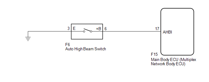
The main body ECU (multiplex network body ECU) detects auto high beam switch signals. The automatic high beam system can be turned on and off by operating the integration control and panel assembly (automatic high beam switch).
WIRING DIAGRAM
CAUTION / NOTICE / HINT
NOTICE:
Before replacing the main body ECU (multiplex network body ECU), refer to refer to registration.*1
- *1: w/ Smart Key System
PROCEDURE
|
1. |
READ VALUE USING Techstream |
(a) Connect the Techstream to the DLC3.
(b) Turn the ignition switch to ON.
(c) Turn the Techstream on.
(d) Enter the following menus: Body Electrical / Main Body / Data List.
(e) Read the Data List according to the display on the Techstream.
Body Electrical > Main Body > Data List|
Tester Display |
Measurement Item |
Range |
Normal Condition |
Diagnostic Note |
|---|---|---|---|---|
|
Auto High Beam Main Switch |
Auto high beam switch signal |
ON or OFF |
ON: Auto high beam switch pressed OFF: Auto high beam switch not pressed |
- |
|
Tester Display |
|---|
|
Auto High Beam Main Switch |
OK:
Normal conditions listed above are displayed.
| OK | .gif) |
PROCEED TO NEXT SUSPECTED AREA SHOWN IN PROBLEM SYMPTOMS TABLE |
|
.gif)
|
2. |
INSPECT AUTO HIGH BEAM SWITCH |
(a) Remove the auto high beam switch.
Click here
.gif)
(b) Inspect the auto high beam switch.
Click here
OK:
Auto high beam switch is normal.
| NG | |
REPLACE AUTO HIGH BEAM SWITCH |
|
|
3. |
CHECK HARNESS AND CONNECTOR (MAIN BODY ECU (MULTIPLEX NETWORK BODY ECU) AND BODY GROUND) |
(a) Disconnect the F15 main body ECU (multiplex network body ECU) connector.
(b) Measure the resistance according to the value(s) in the table below.
Standard Resistance:
|
Tester Connection |
Condition |
Specified Condition |
|---|---|---|
|
F6-6 (+B) - F15-17 (AHBI) |
Always |
Below 1 Ω |
|
F6-6 (+B) or F15-17 (AHBI) - Body ground |
Always |
10 kΩ or higher |
|
F6-3 (E) - Body ground |
Always |
Below 1 Ω |
| OK | |
REPLACE MAIN BODY ECU (MULTIPLEX NETWORK BODY ECU)
|
| NG | |
REPAIR OR REPLACE HARNESS OR CONNECTOR |
 Lost Communication with Front Camera Module (U023A)
DESCRIPTION
This DTC is stored when the CAN communication system is malfunctioning.
DTC No.
Detection Item
DTC Detection Condition
Trouble Area
...

Other materials:
Toyota CH-R Service Manual > Console Box Light: Components
COMPONENTS
ILLUSTRATION
*1
COWL SIDE TRIM BOARD LH
*2
FRONT DOOR SCUFF PLATE LH
*3
INSTRUMENT CLUSTER FINISH PANEL GARNISH ASSEMBLY
*4
INSTRUMENT PANEL BOX ASSEMBLY
*5
INSTRU ...
Toyota CH-R Service Manual > Steering Lock System: Terminals Of Ecu
TERMINALS OF ECU
TERMINAL INSPECTION
*a
Component without harness connected
(Steering Lock ECU (Steering Lock Actuator or Upper Bracket Assembly))
-
-
(a) Measure the voltage and resistance according to the value(s) in the table
below.
...
Toyota C-HR (AX20) 2023-2026 Owner's Manual
Toyota CH-R Owners Manual
- For safety and security
- Instrument cluster
- Operation of each component
- Driving
- Interior features
- Maintenance and care
- When trouble arises
- Vehicle specifications
- For owners
Toyota CH-R Service Manual
- Introduction
- Maintenance
- Audio / Video
- Cellular Communication
- Navigation / Multi Info Display
- Park Assist / Monitoring
- Brake (front)
- Brake (rear)
- Brake Control / Dynamic Control Systems
- Brake System (other)
- Parking Brake
- Axle And Differential
- Drive Shaft / Propeller Shaft
- K114 Cvt
- 3zr-fae Battery / Charging
- Networking
- Power Distribution
- Power Assist Systems
- Steering Column
- Steering Gear / Linkage
- Alignment / Handling Diagnosis
- Front Suspension
- Rear Suspension
- Tire / Wheel
- Tire Pressure Monitoring
- Door / Hatch
- Exterior Panels / Trim
- Horn
- Lighting (ext)
- Mirror (ext)
- Window / Glass
- Wiper / Washer
- Door Lock
- Heating / Air Conditioning
- Interior Panels / Trim
- Lighting (int)
- Meter / Gauge / Display
- Mirror (int)
- Power Outlets (int)
- Pre-collision
- Seat
- Seat Belt
- Supplemental Restraint Systems
- Theft Deterrent / Keyless Entry

0.0089