Toyota CH-R Service Manual: Removal
REMOVAL
PROCEDURE
1. REMOVE BACK DOOR TRIM UPPER PANEL ASSEMBLY
Click here
.gif)
2. REMOVE NO. 2 BACK DOOR PANEL PROTECTOR
Click here
3. REMOVE NO. 1 BACK DOOR PANEL PROTECTOR
HINT:
Use the same procedure as for the No. 2 back door panel protector side.
4. REMOVE REAR SPOILER ASSEMBLY
|
(a) Disconnect the connector. |
|
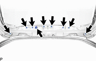
(b) Remove the 8 nuts.
(c) Disengage the clips as shown in the illustration to remove the rear spoiler assembly.
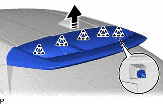
.png) |
Remove in this Direction |
 Components
COMPONENTS
ILLUSTRATION
*1
BACK DOOR TRIM UPPER PANEL ASSEMBLY
*2
NO. 1 BACK DOOR PANEL PROTECTOR
*3
NO. 2 BACK DOOR PANEL P ...
 Disassembly
DISASSEMBLY
PROCEDURE
1. REMOVE NO. 2 REAR SPOILER
(a) Remove the 2 screws.
Remove in this Direction
(b) Disengage the claws to remove the No. 2 rear spoiler as sho ...
Other materials:
Toyota CH-R Service Manual > Audio And Visual System(for Radio And Display Type): Reverse Signal Circuit
DESCRIPTION
The radio and display receiver assembly receives a reverse signal from the park/neutral
position switch.
WIRING DIAGRAM
PROCEDURE
1.
CHECK BACK-UP LIGHT
(a) Move the shift lever to R and check if the back-up lights come on.
OK:
The back-up ligh ...
Toyota CH-R Service Manual > Audio And Visual System(for Radio And Display Type): Certification ECU Vehicle Information Reading/Writing Process Malfunction (B15F7)
DESCRIPTION
This DTC is stored when items controlled by the certification ECU (smart key
ECU assembly) cannot be customized via the audio and visual system vehicle customization
screen.
HINT:
The certification ECU (smart key ECU assembly) controls the smart key system
related items that are ...
Toyota C-HR (AX20) 2023-2026 Owner's Manual
Toyota CH-R Owners Manual
- For safety and security
- Instrument cluster
- Operation of each component
- Driving
- Interior features
- Maintenance and care
- When trouble arises
- Vehicle specifications
- For owners
Toyota CH-R Service Manual
- Introduction
- Maintenance
- Audio / Video
- Cellular Communication
- Navigation / Multi Info Display
- Park Assist / Monitoring
- Brake (front)
- Brake (rear)
- Brake Control / Dynamic Control Systems
- Brake System (other)
- Parking Brake
- Axle And Differential
- Drive Shaft / Propeller Shaft
- K114 Cvt
- 3zr-fae Battery / Charging
- Networking
- Power Distribution
- Power Assist Systems
- Steering Column
- Steering Gear / Linkage
- Alignment / Handling Diagnosis
- Front Suspension
- Rear Suspension
- Tire / Wheel
- Tire Pressure Monitoring
- Door / Hatch
- Exterior Panels / Trim
- Horn
- Lighting (ext)
- Mirror (ext)
- Window / Glass
- Wiper / Washer
- Door Lock
- Heating / Air Conditioning
- Interior Panels / Trim
- Lighting (int)
- Meter / Gauge / Display
- Mirror (int)
- Power Outlets (int)
- Pre-collision
- Seat
- Seat Belt
- Supplemental Restraint Systems
- Theft Deterrent / Keyless Entry

0.009