Toyota CH-R Service Manual: Removal
REMOVAL
CAUTION / NOTICE / HINT
The necessary procedures (adjustment, calibration, initialization, or registration) that must be performed after parts are removed and installed, or replaced during the rear door window frame moulding removal/installation are shown below.
Necessary Procedure After Parts Removed/Installed/Replaced|
Replaced Part or Performed Procedure |
Necessary Procedure |
Effect/Inoperative Function when Necessary Procedure not Performed |
Link |
|---|---|---|---|
|
Disconnect cable from negative battery terminal |
Initialize back door lock |
Power door lock control system |
|
|
Memorize steering angle neutral point |
Lane departure alert system (w/ Steering Control) |
|
|
|
Pre-collision system |
|||
|
Initialize Power Window Control System |
|
|
HINT:
- Use the same procedure for the RH side and LH side.
- The following procedure is for the LH side.
PROCEDURE
1. REMOVE REAR DOOR BELT MOULDING ASSEMBLY
Click here
.gif)
2. REMOVE REAR DOOR WEATHERSTRIP
Click here
3. REMOVE REAR DOOR OUTSIDE MOULDING SUB-ASSEMBLY
HINT:
When removing the rear door outside moulding sub-assembly, heat the vehicle body and rear door outside moulding sub-assembly using a heat light.
Heating Temperature|
Item |
Temperature |
|---|---|
|
Vehicle Body |
40 to 60°C (104 to 140°F) |
|
Rear Door Outside Moulding Sub-assembly |
20 to 30°C (68 to 86°F) |
CAUTION:
- Do not touch the heat light and heated parts, touching the heat light may result in burns.
- Touching heated parts for a long time may result in burns.
.png)
|
*a |
Heated Part |
|
*b |
Heat Light |
NOTICE:
Do not heat the vehicle body or rear door outside moulding sub-assembly excessively.
(a) Using a heat light, heat the rear door outside moulding sub-assembly.
(b) Apply protective tape around the rear door outside moulding sub-assembly as shown in the illustration.
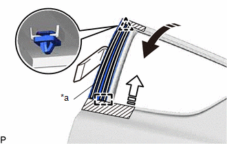
|
*a |
Double-sided Tape |
.png) |
Remove in this Direction (1) |
.png) |
Remove in this Direction (2) |
.png) |
Protective Tape |
(c) Using a moulding remover D, disengage the clip and guide, and separate the double-sided tape and caulking sponge to remove the rear door outside moulding sub-assembly as shown in the illustration.
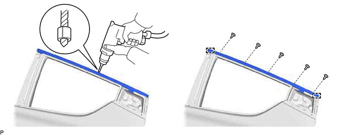
4. REMOVE REAR DOOR UPPER WINDOW FRAME MOULDING
(a) Insert a 4.0 mm (0.157 in.) drill bit into a drill.
|
(b) Tape the 4.0 mm (0.157 in.) drill bit 5.0 mm (0.197 in.) from the tip as shown in the illustration. Standard Measurement:
NOTICE: Tape the 4.0 mm (0.157 in.) drill bit to prevent the drill bit from going too deep. |
|
.png)
(c) Lightly press the drill bit against the rivets to drill off the rivet flanges, and remove the 5 rivets.
CAUTION:
Be careful of the drilled rivets, as they may be hot.
NOTICE:
- Pressing the drill too firmly will cause the rivet to turn and result in the rivet not being drilled through.
- Prying the rivets with the drill may damage the rivet installation holes or drill bit.
(d) Using a vacuum cleaner, remove the rivet fragments and shavings from the drilled areas.
(e) Disengage the guides to remove the rear door upper window frame moulding.
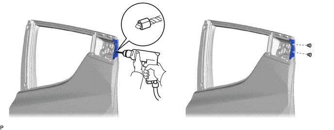
5. REMOVE REAR DOOR REAR WINDOW FRAME MOULDING
(a) Insert a 4.0 mm (0.157 in.) drill bit into a drill.
|
(b) Tape the 4.0 mm (0.157 in.) drill bit 5.0 mm (0.197 in.) from the tip as shown in the illustration. Standard Measurement:
NOTICE: Tape the 4.0 mm (0.157 in.) drill bit to prevent the drill bit from going too deep. |
|
(c) Lightly press the drill bit against the rivets to drill off the rivet flanges, and remove the 2 rivets and rear door rear window frame moulding.
CAUTION:
Be careful of the drilled rivets, as they may be hot.
NOTICE:
- Pressing the drill too firmly will cause the rivet to turn and result in the rivet not being drilled through.
- Prying the rivets with the drill may damage the rivet installation holes or drill bit.
(d) Using a vacuum cleaner, remove the rivet fragments and shavings from the drilled areas.
 Components
COMPONENTS
ILLUSTRATION
*1
REAR DOOR OUTSIDE MOULDING SUB-ASSEMBLY
*2
REAR DOOR REAR WINDOW FRAME MOULDING
*3
REAR DOOR UPPE ...
 Installation
INSTALLATION
CAUTION / NOTICE / HINT
HINT:
Use the same procedure for the RH side and LH side.
The following procedure is for the LH side.
PROCEDURE
1. INSTALL REAR DOOR REAR WI ...
Other materials:
Toyota CH-R Service Manual > Lighting System: Open in IG Circuit (B242E)
DESCRIPTION
This DTC is stored when a malfunction occurs in the headlight ECU sub-assembly
LH IG power source circuit. The headlight ECU sub-assembly LH stores DTC B242E.
DTC No.
Detection Item
DTC Detection Condition
Trouble Area
Note
...
Toyota CH-R Service Manual > Meter / Gauge System: Precaution
PRECAUTION
FUEL RECEIVER GAUGE OPERATION
(a) OPERATION
The combination meter assembly uses the fuel injection volume signal from the
ECM, fuel sender gauge assembly to detect the amount of fuel remaining in the fuel
tank assembly. Each gauge assembly has a variable resistor whose resistance c ...
Toyota C-HR (AX20) 2023-2026 Owner's Manual
Toyota CH-R Owners Manual
- For safety and security
- Instrument cluster
- Operation of each component
- Driving
- Interior features
- Maintenance and care
- When trouble arises
- Vehicle specifications
- For owners
Toyota CH-R Service Manual
- Introduction
- Maintenance
- Audio / Video
- Cellular Communication
- Navigation / Multi Info Display
- Park Assist / Monitoring
- Brake (front)
- Brake (rear)
- Brake Control / Dynamic Control Systems
- Brake System (other)
- Parking Brake
- Axle And Differential
- Drive Shaft / Propeller Shaft
- K114 Cvt
- 3zr-fae Battery / Charging
- Networking
- Power Distribution
- Power Assist Systems
- Steering Column
- Steering Gear / Linkage
- Alignment / Handling Diagnosis
- Front Suspension
- Rear Suspension
- Tire / Wheel
- Tire Pressure Monitoring
- Door / Hatch
- Exterior Panels / Trim
- Horn
- Lighting (ext)
- Mirror (ext)
- Window / Glass
- Wiper / Washer
- Door Lock
- Heating / Air Conditioning
- Interior Panels / Trim
- Lighting (int)
- Meter / Gauge / Display
- Mirror (int)
- Power Outlets (int)
- Pre-collision
- Seat
- Seat Belt
- Supplemental Restraint Systems
- Theft Deterrent / Keyless Entry

0.009