
Toyota CH-R Service Manual: Installation
INSTALLATION
PROCEDURE
1. INSTALL NO. 2 BACK DOOR GARNISH RETAINER
(a) Engage the claws to install the No. 2 back door garnish retainer as shown in the illustration.
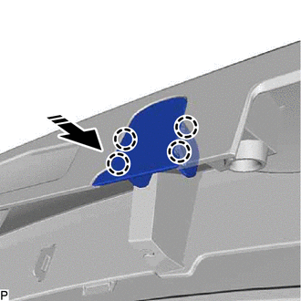
.png) |
Install in this Direction |
2. INSTALL BACK DOOR OUTSIDE GARNISH SUB-ASSEMBLY
(a) Remove the release paper from the back door outside garnish seal.
(b) Engage the clips to install the back door outside garnish as shown in the illustration.
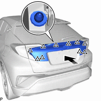
|
|
Install in this Direction |
(c) Install the 4 bolts.
Torque:
4.9 N·m {50 kgf·cm, 43 in·lbf}
3. INSTALL BACK DOOR TRIM PANEL ASSEMBLY
Click here
.gif)
4. INSTALL BACK DOOR SIDE GARNISH LH
Click here
5. INSTALL BACK DOOR SIDE GARNISH RH
HINT:
Use the same procedure as for the LH side.
6. INSTALL BACK DOOR TRIM UPPER PANEL ASSEMBLY
Click here
7. INSTALL TONNEAU COVER ASSEMBLY (w/ Tonneau Cover)
Click here
8. INSTALL PACKAGE TRAY TRIM PANEL ASSEMBLY (w/ Package Tray Trim)
Click here
 Reassembly
REASSEMBLY
PROCEDURE
1. INSTALL NO. 1 BACK DOOR EMBLEM
Click here
2. INSTALL NO. 2 BACK DOOR NAME PLATE
Click here
3. INSTALL NO. 1 BACK DOOR NAME PLATE
Click here
4. INSTALL BACK ...

Other materials:
Toyota CH-R Service Manual > Smart Key System(for Entry Function): Open in Inside Luggage Compartment Electrical Key Oscillator Circuit (B27A7)
DESCRIPTION
The certification ECU (smart key ECU assembly) generates a request signal and
transmits the signal to the No. 3 indoor electrical key antenna assembly (inside
luggage compartment). For the No. 3 indoor electrical key antenna assembly (inside
luggage compartment) to detect when the ...
Toyota CH-R Service Manual > Power Door Lock Control System: Operation Check
OPERATION CHECK
CHECK POWER DOOR LOCK OPERATION
NOTICE:
The operation check below is based on the non-customized initial condition of
the vehicle.
(a) Check basic functions.
(1) Check that all of the doors lock when the lock side of the door control switch
is pressed.
(2) Check that all of ...
Toyota C-HR (AX20) 2023-2026 Owner's Manual
Toyota CH-R Owners Manual
- For safety and security
- Instrument cluster
- Operation of each component
- Driving
- Interior features
- Maintenance and care
- When trouble arises
- Vehicle specifications
- For owners
Toyota CH-R Service Manual
- Introduction
- Maintenance
- Audio / Video
- Cellular Communication
- Navigation / Multi Info Display
- Park Assist / Monitoring
- Brake (front)
- Brake (rear)
- Brake Control / Dynamic Control Systems
- Brake System (other)
- Parking Brake
- Axle And Differential
- Drive Shaft / Propeller Shaft
- K114 Cvt
- 3zr-fae Battery / Charging
- Networking
- Power Distribution
- Power Assist Systems
- Steering Column
- Steering Gear / Linkage
- Alignment / Handling Diagnosis
- Front Suspension
- Rear Suspension
- Tire / Wheel
- Tire Pressure Monitoring
- Door / Hatch
- Exterior Panels / Trim
- Horn
- Lighting (ext)
- Mirror (ext)
- Window / Glass
- Wiper / Washer
- Door Lock
- Heating / Air Conditioning
- Interior Panels / Trim
- Lighting (int)
- Meter / Gauge / Display
- Mirror (int)
- Power Outlets (int)
- Pre-collision
- Seat
- Seat Belt
- Supplemental Restraint Systems
- Theft Deterrent / Keyless Entry

0.0085