Toyota CH-R Service Manual: Components
COMPONENTS
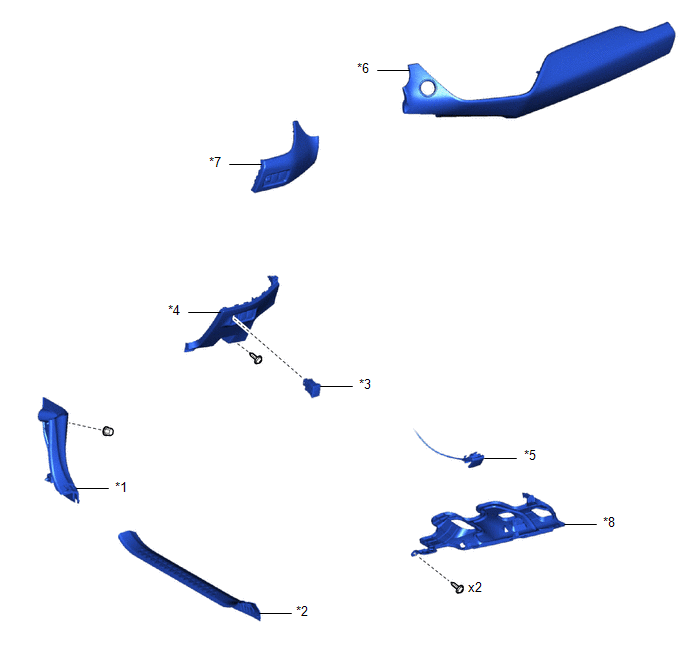
ILLUSTRATION
|
*1 |
COWL SIDE TRIM BOARD LH |
*2 |
FRONT DOOR SCUFF PLATE LH |
|
*3 |
FUEL LID OPENER SWITCH |
*4 |
FUSE BOX OPENING COVER |
|
*5 |
HOOD LOCK CONTROL LEVER SUB-ASSEMBLY |
*6 |
INSTRUMENT CLUSTER FINISH PANEL GARNISH ASSEMBLY |
|
*7 |
INSTRUMENT CLUSTER FINISH PANEL SUB-ASSEMBLY |
*8 |
NO. 1 INSTRUMENT PANEL UNDER COVER SUB-ASSEMBLY |

 Removal
REMOVAL
PROCEDURE
1. REMOVE FRONT DOOR SCUFF PLATE LH
Click here
2. REMOVE COWL SIDE TRIM BOARD LH
Click here
3. REMOVE NO. 1 INSTRUMENT PANEL UNDER COVER SUB-ASSEMBLY
Click here
...
Other materials:
Toyota CH-R Service Manual > Tire Pressure Warning System: Transmitter ID not Received in Main Mode (C2126/26)
DESCRIPTION
After all IDs are registered, DTC C2126/26 is stored in the tire pressure warning
ECU and receiver and the tire pressure warning light blinks for 1 minute and then
illuminates.
When the tire pressure warning ECU and receiver successfully receives radio waves
from all the transmit ...
Toyota CH-R Service Manual > Knee Airbag Assembly: On-vehicle Inspection
ON-VEHICLE INSPECTION
CAUTION / NOTICE / HINT
CAUTION:
Be sure to correctly follow the removal and installation procedures for the lower
No. 1 instrument panel airbag assembly.
PROCEDURE
1. INSPECT LOWER NO. 1 INSTRUMENT PANEL AIRBAG ASSEMBLY (for Vehicle not Involved
in Collision)
(a) Per ...
Toyota C-HR (AX20) 2023-2026 Owner's Manual
Toyota CH-R Owners Manual
- For safety and security
- Instrument cluster
- Operation of each component
- Driving
- Interior features
- Maintenance and care
- When trouble arises
- Vehicle specifications
- For owners
Toyota CH-R Service Manual
- Introduction
- Maintenance
- Audio / Video
- Cellular Communication
- Navigation / Multi Info Display
- Park Assist / Monitoring
- Brake (front)
- Brake (rear)
- Brake Control / Dynamic Control Systems
- Brake System (other)
- Parking Brake
- Axle And Differential
- Drive Shaft / Propeller Shaft
- K114 Cvt
- 3zr-fae Battery / Charging
- Networking
- Power Distribution
- Power Assist Systems
- Steering Column
- Steering Gear / Linkage
- Alignment / Handling Diagnosis
- Front Suspension
- Rear Suspension
- Tire / Wheel
- Tire Pressure Monitoring
- Door / Hatch
- Exterior Panels / Trim
- Horn
- Lighting (ext)
- Mirror (ext)
- Window / Glass
- Wiper / Washer
- Door Lock
- Heating / Air Conditioning
- Interior Panels / Trim
- Lighting (int)
- Meter / Gauge / Display
- Mirror (int)
- Power Outlets (int)
- Pre-collision
- Seat
- Seat Belt
- Supplemental Restraint Systems
- Theft Deterrent / Keyless Entry

0.008