Toyota CH-R Service Manual: Back Door Support
Components
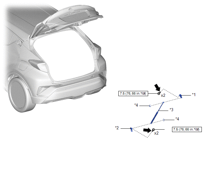
COMPONENTS
ILLUSTRATION
|
*1 |
BACK DOOR DAMPER STAY LOWER BRACKET |
*2 |
BACK DOOR DAMPER STAY UPPER BRACKET |
|
*3 |
BACK DOOR STAY ASSEMBLY |
*4 |
STOP RING |
.png) |
N*m (kgf*cm, ft.*lbf): Specified torque |
.png) |
Toyota Genuine Adhesive 1324, Three Bond 1324 or equivalent |
|
★ |
Precoated part |
- |
- |
Installation
INSTALLATION
CAUTION / NOTICE / HINT
HINT:
- Use the same procedure for the RH side and LH side.
- The following procedure is for the LH side.
PROCEDURE
1. INSTALL BACK DOOR DAMPER STAY LOWER BRACKET
(a) Clean the threaded portion on the vehicle body with non-residue solvent.
(b) Apply adhesive to the threads of the 2 bolts.
Adhesive:
Toyota Genuine Adhesive 1324, Three Bond 1324 or equivalent
(c) Install the 2 bolts and back door damper stay lower bracket.
Torque:
7.5 N·m {76 kgf·cm, 66 in·lbf}
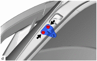
2. INSTALL BACK DOOR DAMPER STAY UPPER BRACKET
(a) Clean the threaded portion on the vehicle body with non-residue solvent.
(b) Apply adhesive to the threads of the 2 bolts.
Adhesive:
Toyota Genuine Adhesive 1324, Three Bond 1324 or equivalent
(c) Install the back door damper stay upper bracket with the 2 bolts.
Torque:
7.5 N·m {76 kgf·cm, 66 in·lbf}
3. INSTALL BACK DOOR STAY ASSEMBLY
CAUTION:
- Do not perform work if the back door is not securely supported.
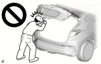
- The back door could fall, resulting in injury.
NOTICE:
- Avoid touching the piston rod as much as possible to prevent foreign matter from attaching to it. Be sure to hold the cylinder while servicing.
- Do not wear cotton gloves or other similar materials when handling the piston rod. Fibers may attach to the rod and result in gas leaks.
- Do not apply any horizontal load to the door stay in order to prevent the piston rod from deforming.
(a) When reusing the back door stay assembly:
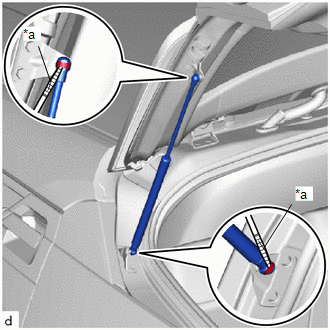
(1) Install the 2 stop rings to the back door stay assembly.
|
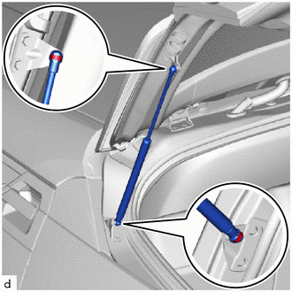
(b) Install the back door stay assembly. NOTICE:
|
|
Removal
REMOVAL
CAUTION / NOTICE / HINT
HINT:
- Use the same procedure for the RH side and LH side.
- The following procedure is for the LH side.
PROCEDURE
1. REMOVE BACK DOOR STAY ASSEMBLY
CAUTION:
- Do not perform work if the back door is not securely supported.
.png)
- The back door could fall, resulting in injury.
NOTICE:
- Avoid touching the piston rod as much as possible to prevent foreign matter from attaching to it. Be sure to hold the cylinder while servicing.
- Do not wear cotton gloves or other similar materials when handling the piston rod. Fibers may attach to the rod and result in gas leaks.
- Do not apply any horizontal load to the door stay in order to prevent the piston rod from deforming.
|
(a) Using a screwdriver with its tip wrapped in protective tape, remove the 2 stop rings as shown in the illustration. |
|
(b) Release the ball joint to remove the back door stay assembly.
NOTICE:
- Remove the back door stay assembly while supporting the back door by hand.
- Remove the back door stay assembly while supporting the back door stay assembly by hand.
2. REMOVE BACK DOOR DAMPER STAY UPPER BRACKET
|
(a) Remove the 2 bolts and back door damper stay upper bracket. |
|
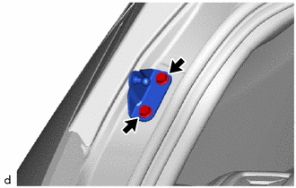
3. REMOVE BACK DOOR DAMPER STAY LOWER BRACKET
|
(a) Remove the 2 bolts and back door damper stay lower bracket. |
|
Disposal
DISPOSAL
PROCEDURE
1. DISPOSE OF OF BACK DOOR STAY ASSEMBLY
(a) Fully extend the back door stay assembly.
(b) Secure the back door stay assembly horizontally in a vise with the piston rod pulled out.
(c) Wearing protective glass, gradually cut the shaded part between "A" and "B" shown the illustration using a metal saw to gradually release the gas.
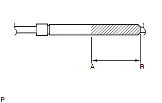
Specification:
|
Area |
Measurement |
|---|---|
|
A - B |
53.5 mm (2.11 in.) |
CAUTION:
Always use proper safety equipment and be careful when drilling because shards of metal way fly about.
.png)
HINT:
The gas is colorless, odorless and non-poisonous.
 Back Door Opener Switch
Components
COMPONENTS
ILLUSTRATION
*1
BACK DOOR OPENER SWITCH ASSEMBLY
-
-
Removal
REMOVAL
PROCEDURE
1. REMOVE BACK DOOR OUTSIDE GARNI ...
 Back Door Weatherstrip
Components
COMPONENTS
ILLUSTRATION
*1
BACK DOOR WEATHERSTRIP
-
-
●
Non-reusable part
-
-
...
Other materials:
Toyota CH-R Service Manual > Safety Connect System: How To Proceed With Troubleshooting
CAUTION / NOTICE / HINT
HINT:
Use the following procedure to troubleshoot the safety connect system.
*: Use the Techstream.
PROCEDURE
1.
VEHICLE BROUGHT TO WORKSHOP
NEXT
...
Toyota CH-R Owners Manual > If you have a flat tire: Installing the spare tire
1. Remove any dirt or foreign matter from the wheel contact surface.
If foreign matter is on the wheel contact surface, the wheel nuts may loosen
while the vehicle is in motion, causing the tire to come off.
2. Install the tire and loosely tighten each wheel nut by hand by approximately
th ...
Toyota C-HR (AX20) 2023-2026 Owner's Manual
Toyota CH-R Owners Manual
- For safety and security
- Instrument cluster
- Operation of each component
- Driving
- Interior features
- Maintenance and care
- When trouble arises
- Vehicle specifications
- For owners
Toyota CH-R Service Manual
- Introduction
- Maintenance
- Audio / Video
- Cellular Communication
- Navigation / Multi Info Display
- Park Assist / Monitoring
- Brake (front)
- Brake (rear)
- Brake Control / Dynamic Control Systems
- Brake System (other)
- Parking Brake
- Axle And Differential
- Drive Shaft / Propeller Shaft
- K114 Cvt
- 3zr-fae Battery / Charging
- Networking
- Power Distribution
- Power Assist Systems
- Steering Column
- Steering Gear / Linkage
- Alignment / Handling Diagnosis
- Front Suspension
- Rear Suspension
- Tire / Wheel
- Tire Pressure Monitoring
- Door / Hatch
- Exterior Panels / Trim
- Horn
- Lighting (ext)
- Mirror (ext)
- Window / Glass
- Wiper / Washer
- Door Lock
- Heating / Air Conditioning
- Interior Panels / Trim
- Lighting (int)
- Meter / Gauge / Display
- Mirror (int)
- Power Outlets (int)
- Pre-collision
- Seat
- Seat Belt
- Supplemental Restraint Systems
- Theft Deterrent / Keyless Entry

0.0086