Toyota CH-R Service Manual: Back Door Opener Switch
Components
COMPONENTS
ILLUSTRATION

|
*1 |
BACK DOOR OPENER SWITCH ASSEMBLY |
- |
- |
Removal
REMOVAL
PROCEDURE
1. REMOVE BACK DOOR OUTSIDE GARNISH SUB-ASSEMBLY
Click here
.gif)
2. REMOVE BACK DOOR OPENER SWITCH ASSEMBLY
|
(a) Disconnect the connector. |
|
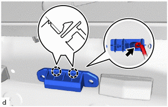
(b) Disengage the claws to remove the back door opener switch assembly.
Inspection
INSPECTION
PROCEDURE
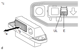
1. INSPECT BACK DOOR OPENER SWITCH ASSEMBLY (w/ Smart Key System)
|
(a) Check the operation of the back door opener switch. (1) Measure the resistance according to the value(s) in the table below. Standard Resistance:
If the result is not as specified, replace the back door opener switch assembly. |
|
|
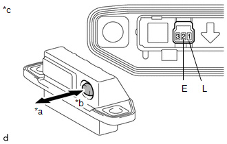
(b) Check the operation of the back door lock switch. (1) Measure the resistance according to the value(s) in the table below. Standard Resistance:
If the result is not as specified, replace the back door opener switch assembly. |
|
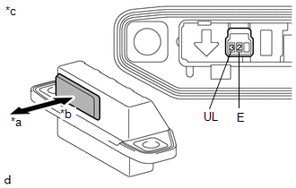
2. INSPECT BACK DOOR OPENER SWITCH ASSEMBLY (w/o Smart Key System)
|
(a) Check the operation of the back door opener switch. (1) Measure the resistance according to the value(s) in the table below. Standard Resistance:
If the result is not as specified, replace the back door opener switch assembly. |
|
Installation
INSTALLATION
PROCEDURE
1. INSTALL BACK DOOR OPENER SWITCH ASSEMBLY
|
(a) Engage the claws to install the back door opener switch assembly. |
|
.png)
(b) Connect the connector.
2. INSTALL BACK DOOR OUTSIDE GARNISH SUB-ASSEMBLY
Click here
.gif)
 Reassembly
REASSEMBLY
PROCEDURE
1. INSTALL NO. 1 BACK DOOR EMBLEM
Click here
2. INSTALL NO. 2 BACK DOOR NAME PLATE
Click here
3. INSTALL NO. 1 BACK DOOR NAME PLATE (w/ Brand Mark)
Click here
...
 Back Door Support
Components
COMPONENTS
ILLUSTRATION
*1
BACK DOOR DAMPER STAY LOWER BRACKET
*2
BACK DOOR DAMPER STAY UPPER BRACKET
*3
BACK ...
Other materials:
Toyota CH-R Service Manual > Occupant Classification System: Terminals Of Ecu
TERMINALS OF ECU
OCCUPANT DETECTION ECU
Terminal No. (Symbol)
Wiring Color
Terminal Description
Condition
Specified Condition
Y5-1 (SVC1) - Y5-5 (SGD1)
R - G
Front in weight detection sensor sub-assembl ...
Toyota CH-R Owners Manual > Side doors: Rear door child-protector lock
The door cannot be opened from inside the vehicle when the lock is set.
Unlock
Lock
These locks can be set to prevent children from opening the rear doors. Push
down on each rear door switch to lock both rear doors.
■Switching the door unlock function (vehicles with a smart key sys ...
Toyota C-HR (AX20) 2023-2026 Owner's Manual
Toyota CH-R Owners Manual
- For safety and security
- Instrument cluster
- Operation of each component
- Driving
- Interior features
- Maintenance and care
- When trouble arises
- Vehicle specifications
- For owners
Toyota CH-R Service Manual
- Introduction
- Maintenance
- Audio / Video
- Cellular Communication
- Navigation / Multi Info Display
- Park Assist / Monitoring
- Brake (front)
- Brake (rear)
- Brake Control / Dynamic Control Systems
- Brake System (other)
- Parking Brake
- Axle And Differential
- Drive Shaft / Propeller Shaft
- K114 Cvt
- 3zr-fae Battery / Charging
- Networking
- Power Distribution
- Power Assist Systems
- Steering Column
- Steering Gear / Linkage
- Alignment / Handling Diagnosis
- Front Suspension
- Rear Suspension
- Tire / Wheel
- Tire Pressure Monitoring
- Door / Hatch
- Exterior Panels / Trim
- Horn
- Lighting (ext)
- Mirror (ext)
- Window / Glass
- Wiper / Washer
- Door Lock
- Heating / Air Conditioning
- Interior Panels / Trim
- Lighting (int)
- Meter / Gauge / Display
- Mirror (int)
- Power Outlets (int)
- Pre-collision
- Seat
- Seat Belt
- Supplemental Restraint Systems
- Theft Deterrent / Keyless Entry

0.0069