Toyota CH-R Service Manual: TC and CG Terminal Circuit
DESCRIPTION
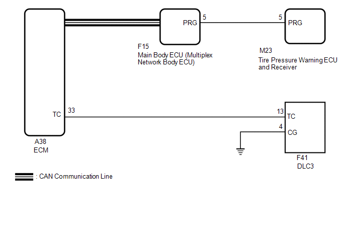
DTC output mode is set by connecting terminals 13 (TC) and 4 (CG) of the DLC3. The DTCs are indicated by the blinking of the tire pressure warning light.
WIRING DIAGRAM
CAUTION / NOTICE / HINT
NOTICE:
- When replacing the tire pressure warning ECU and receiver, read the
transmitter IDs stored in the old ECU using the Techstream and write them
down before removal.
Click here
.gif)
- It is necessary to perform initialization
after registration
of the transmitter IDs into the tire pressure warning ECU and receiver if
the ECU has been replaced.
PROCEDURE
|
1. |
CHECK CAN COMMUNICATION SYSTEM |
(a) Check if a CAN communication system DTC is output.
Click here
|
Result |
Proceed to |
|---|---|
|
DTCs are not output. |
A |
|
DTCs are output. |
B |
| B | .gif) |
GO TO CAN COMMUNICATION SYSTEM
|
|
.gif)
|
2. |
CHECK DTC (C2179/79) |
(a) Check if DTC C2179/79 is output.
Click here
|
Result |
Proceed to |
|---|---|
|
DTC C2179/79 is not output. |
A |
|
DTC C2179/79 is output. |
B |
| B | |
GO TO DTC C2179/79 |
|
|
3. |
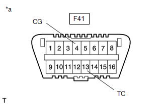
CHECK HARNESS AND CONNECTOR (TC of DLC3 - ECM) |
(a) Disconnect the A38 ECM connector.
(b) Measure the resistance according to the value(s) in the table below.
Standard Resistance:
|
Tester Connection |
Condition |
Specified Condition |
|---|---|---|
|
F41-13 (TC) - A38-33 (TC) |
Always |
Below 1 Ω |
|
F41-13 (TC) or A38-33 (TC) - Body ground |
Always |
10 kΩ or higher |
| NG | |
REPAIR OR REPLACE HARNESS OR CONNECTOR |
|
|
4. |
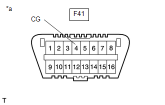
CHECK HARNESS AND CONNECTOR (CG of DLC3 - BODY GROUND) |
|
(a) Measure the resistance according to the value(s) in the table below. Standard Resistance:
|
|
| NG | |
REPAIR OR REPLACE HARNESS OR CONNECTOR |
|
|
5. |
INSPECT DLC3 TERMINAL VOLTAGE (TC VOLTAGE) |
(a) Reconnect the A38 ECM connector.
|
(b) Measure the voltage according to the value(s) in the table below. Standard Voltage:
|
|
| OK | |
PROCEED TO NEXT SUSPECTED AREA SHOWN IN PROBLEM SYMPTOMS TABLE |
| NG | |
REPLACE ECM
|
 Tire Pressure Warning Light Circuit
DESCRIPTION
If the tire pressure warning ECU and receiver detects any problems, the tire
pressure warning light blinks (stays on after blinking for 1 minute) and tire pressure
monitoring is cance ...

Other materials:
Toyota CH-R Owners Manual > Tire information: Typical DOT and Tire Identification Number (TIN)
Type A
Type B
DOT symbol*
Tire Identification Number (TIN)
Tire manufacturer's identification mark
Tire size code
Manufacturer's optional tire type code (3 or 4 letters)
Manufacturing week
Manufacturing year
Manufacturer's code
*: The DOT symbol certifies th ...
Toyota CH-R Service Manual > Rear View Monitor System: Parts Location
PARTS LOCATION
ILLUSTRATION
*1
PARK/NEUTRAL POSITION SWITCH
*2
REAR TELEVISION CAMERA ASSEMBLY
ILLUSTRATION
*1
RADIO AND DISPLAY RECEIVER ASSEMBLY
*2
INSTRUMENT PANEL JUNCTION BLOCK ASSEMBLY
- ...
Toyota C-HR (AX20) 2023-2026 Owner's Manual
Toyota CH-R Owners Manual
- For safety and security
- Instrument cluster
- Operation of each component
- Driving
- Interior features
- Maintenance and care
- When trouble arises
- Vehicle specifications
- For owners
Toyota CH-R Service Manual
- Introduction
- Maintenance
- Audio / Video
- Cellular Communication
- Navigation / Multi Info Display
- Park Assist / Monitoring
- Brake (front)
- Brake (rear)
- Brake Control / Dynamic Control Systems
- Brake System (other)
- Parking Brake
- Axle And Differential
- Drive Shaft / Propeller Shaft
- K114 Cvt
- 3zr-fae Battery / Charging
- Networking
- Power Distribution
- Power Assist Systems
- Steering Column
- Steering Gear / Linkage
- Alignment / Handling Diagnosis
- Front Suspension
- Rear Suspension
- Tire / Wheel
- Tire Pressure Monitoring
- Door / Hatch
- Exterior Panels / Trim
- Horn
- Lighting (ext)
- Mirror (ext)
- Window / Glass
- Wiper / Washer
- Door Lock
- Heating / Air Conditioning
- Interior Panels / Trim
- Lighting (int)
- Meter / Gauge / Display
- Mirror (int)
- Power Outlets (int)
- Pre-collision
- Seat
- Seat Belt
- Supplemental Restraint Systems
- Theft Deterrent / Keyless Entry

0.0087