Toyota CH-R Service Manual: System Description
SYSTEM DESCRIPTION
DESCRIPTION OF SYSTEM
(a) The tire pressure warning system warns the driver when the tire pressure has decreased in order to decrease CO2 emissions and enhance safety.
(b) The tire pressure warning system illuminates the tire pressure warning light to warn the driver when the following condition is met:
- Due to the operation of the steering pad switch assembly, the tire pressure
drops to approximately 75% or less of the tire pressure set during system
initialization.
HINT:
The tire pressure warning pressure (pressure at which the tire pressure warning light is illuminated) cannot be set to approximately 75% or less of a specified tire pressure value.
(c) When the tire pressure warning system detects that the tire pressure of a tire is lower than the threshold, it will inform the driver using a warning light.
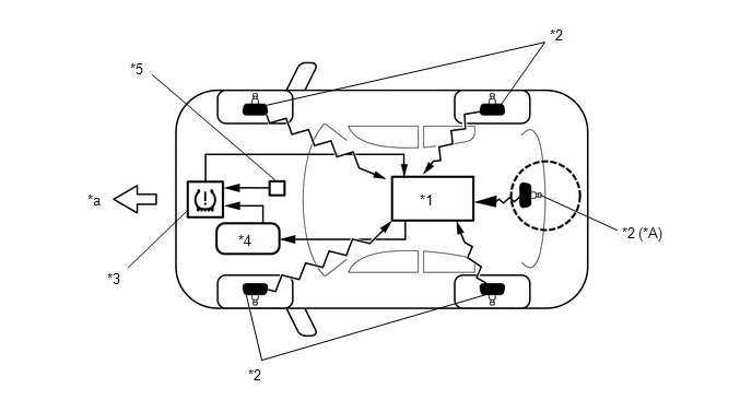
(d) The tire pressure warning ECU and receiver receives the transmitter ID, temperature and tire pressure information from the tire pressure warning valve and transmitters shown in the following illustration. This information is used to determine when the pressure in one of the tires has dropped.
|
*A |
w/ Full Size Spare Tire |
- |
- |
|
*1 |
Tire Pressure Warning ECU and Receiver |
*2 |
Tire Pressure Warning Valve and Transmitter |
|
*3 |
Combination Meter Assembly - Tire Pressure Warning Light |
*4 |
Main Body ECU (Multiplex Network Body ECU) |
|
*5 |
Steering Pad Switch Assembly |
- |
- |
|
*a |
Front |
- |
- |
DESCRIPTION OF REGISTRATION
(a) When tires and wheels are replaced, always ensure that each transmitter ID is correctly registered.
(b) When one or more of the tire pressure warning valve and transmitters or the tire pressure warning ECU and receiver is replaced, the transmitter IDs for all of the tire pressure warning valve and transmitters must be re-registered. Before registering the transmitter ID of the new tire pressure warning valve and transmitter, check the Data List and record all of the transmitter IDs that are already registered.
Click here
.gif)
TIRE PRESSURE WARNING RESET SWITCH
(a) By operating the steering pad switch assembly, the tire pressure warning ECU and receiver can be set to issue a warning at an inflation pressure that corresponds to the type of tires fitted to the vehicle. Therefore, the warning threshold must be set to the proper value in order to comply with local regulations.
(b) After the inflation pressures of all tires (except the compact spare tire) have been adjusted to the appropriate tire pressures, operate the steering pad switch assembly and perform initialization.
DESCRIPTION OF INITIALIZATION
(a) During initialization, the tire pressure warning valve and transmitters measure the inflation pressure of the tires, and register the signals that are transmitted into the tire pressure warning ECU and receiver at a frequency of about once per minute. The initialization process is completed when signals from all tires (except the compact spare tire) have been received.
(b) Perform initialization in the following cases:
(1) Before delivery of a new vehicle.
(2) After replacement of the tire pressure warning ECU and receiver*.
(3) After replacement of a tire pressure warning valve and transmitter*.
(4) When the specified tire pressure changes due to the use of a different size or type of tire.
(5) When the specified tire pressure changes due to a change in the vehicle load, the speed range that the vehicle will be used in, etc.
(6) When a tire rotation is performed and the specified tire pressures are different for the front and rear of the vehicle.
HINT:
*: Perform initialization after the transmitter ID registration is completed.
FUNCTION OF MAIN COMPONENTS
|
Component |
Function |
|---|---|
|
Tire Pressure Warning Valve and Transmitter |
|
|
Tire Pressure Warning ECU and Receiver |
|
|
Steering Pad Switch Assembly |
Switch that operates the multi-information display. "ENTER" switch:
|
|
Combination Meter Assembly |
Transmits the vehicle speed signal to the tire pressure warning ECU and receiver. |
|
Tire Pressure Warning Light |
|
|
Main Body ECU (Multiplex Network Body ECU) |
|
 System Diagram
SYSTEM DIAGRAM
HINT:
Each tire pressure warning valve and transmitter sends its transmitter ID, temperature
and tire pressure information to the tire pressure warning ECU and receiver.
...
 How To Proceed With Troubleshooting
CAUTION / NOTICE / HINT
HINT:
Use the following procedure to troubleshoot the tire pressure warning
system.
Make sure that the wireless door lock control system has exited diagnostic ...
Other materials:
Toyota CH-R Service Manual > Audio And Visual System(for Radio And Display Type): Operation Check
OPERATION CHECK
STORAGE CHECK (DCU STORAGE CHECK)
NOTICE:
When replacing the radio and display receiver assembly, always replace it with
a new one. If a radio and display receiver assembly which was installed to another
vehicle is used, the following may occur:
A communication malfunc ...
Toyota CH-R Service Manual > Rain Sensor: Installation
INSTALLATION
PROCEDURE
1. INSTALL RAIN SENSOR TAPE
HINT:
The rain sensor tape is reusable. Only replace the tape if it is damaged or contaminated
with foreign matter.
(a) Remove the rain sensor tape.
(b) Clean the rain sensor sensing portion with a piece of cloth.
(c) Peel off th ...
Toyota C-HR (AX20) 2023-2026 Owner's Manual
Toyota CH-R Owners Manual
- For safety and security
- Instrument cluster
- Operation of each component
- Driving
- Interior features
- Maintenance and care
- When trouble arises
- Vehicle specifications
- For owners
Toyota CH-R Service Manual
- Introduction
- Maintenance
- Audio / Video
- Cellular Communication
- Navigation / Multi Info Display
- Park Assist / Monitoring
- Brake (front)
- Brake (rear)
- Brake Control / Dynamic Control Systems
- Brake System (other)
- Parking Brake
- Axle And Differential
- Drive Shaft / Propeller Shaft
- K114 Cvt
- 3zr-fae Battery / Charging
- Networking
- Power Distribution
- Power Assist Systems
- Steering Column
- Steering Gear / Linkage
- Alignment / Handling Diagnosis
- Front Suspension
- Rear Suspension
- Tire / Wheel
- Tire Pressure Monitoring
- Door / Hatch
- Exterior Panels / Trim
- Horn
- Lighting (ext)
- Mirror (ext)
- Window / Glass
- Wiper / Washer
- Door Lock
- Heating / Air Conditioning
- Interior Panels / Trim
- Lighting (int)
- Meter / Gauge / Display
- Mirror (int)
- Power Outlets (int)
- Pre-collision
- Seat
- Seat Belt
- Supplemental Restraint Systems
- Theft Deterrent / Keyless Entry

0.0128