Toyota CH-R Service Manual: Removal
REMOVAL
CAUTION / NOTICE / HINT
The necessary procedures (adjustment, calibration, initialization, or registration) that must be performed after parts are removed and installed, or replaced during rear suspension member sub-assembly removal/installation are shown below.
Necessary Procedures After Parts Removed/Installed/Replaced|
Replaced Part or Performed Procedure |
Necessary Procedure |
Effect/Inoperative Function when Necessary Procedure not Performed |
Link |
|---|---|---|---|
|
Rear wheel alignment adjustment |
|
|
|
|
Initialize No. 1 headlight ECU sub-assembly LH |
Automatic headlight beam level control system |
|
|
Gas leak from exhaust system is repaired |
Inspection After Repair |
|
|
- *1 w/ Height Control Sensor
CAUTION:
To prevent burns, do not touch the engine, exhaust pipe or other high temperature components while the engine is hot.
.png)
PROCEDURE
1. REMOVE REAR WHEEL
Click here
.gif)
2. REMOVE TAIL EXHAUST PIPE ASSEMBLY
Click here
3. SEPARATE REAR FLEXIBLE HOSE LH
(a) Remove the bolt and separate the rear flexible hose LH from the flexible hose bracket.
4. SEPARATE REAR FLEXIBLE HOSE RH
HINT:
Perform the same procedure as for the LH side.
5. REMOVE REAR HEIGHT CONTROL SENSOR SUB-ASSEMBLY LH (w/ Height Control Sensor)
Click here
6. REMOVE REAR STABILIZER LINK ASSEMBLY LH
Click here
7. REMOVE REAR STABILIZER LINK ASSEMBLY RH
HINT:
Perform the same procedure as for the LH side.
8. REMOVE REAR STABILIZER BAR
Click here
9. REMOVE REAR COIL SPRING LH
Click here
10. REMOVE REAR COIL SPRING RH
HINT:
Perform the same procedure as for the LH side.
11. REMOVE REAR LOWER COIL SPRING INSULATOR LH
Click here
12. REMOVE REAR LOWER COIL SPRING INSULATOR RH
HINT:
Perform the same procedure as for the LH side.
13. REMOVE REAR NO. 2 SUSPENSION ARM ASSEMBLY LH
Click here
14. REMOVE REAR NO. 2 SUSPENSION ARM ASSEMBLY RH
HINT:
Perform the same procedure as for the LH side.
15. REMOVE REAR NO. 1 SUSPENSION ARM ASSEMBLY LH
Click here
16. REMOVE REAR NO. 1 SUSPENSION ARM ASSEMBLY RH
HINT:
Perform the same procedure as for the LH side.
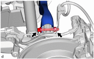
17. SEPARATE REAR UPPER CONTROL ARM ASSEMBLY LH
|
(a) Remove the bolt and nut and separate the rear upper control arm assembly LH from the rear axle carrier sub-assembly LH. NOTICE: Because the nut has its own stopper, do not turn the nut. Loosen the bolt with the nut secured. |
|
18. SEPARATE REAR UPPER CONTROL ARM ASSEMBLY RH
HINT:
Use the same procedure as for the LH side.
19. REMOVE REAR SUSPENSION MEMBER SUB-ASSEMBLY
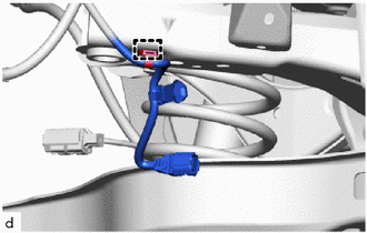
(a) w/ Height Control Sensor:
|
(1) Disengage the clamp to separate the height control sensor wire harness. |
|
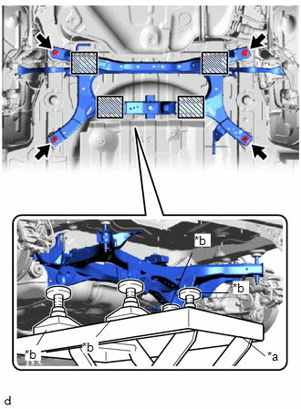
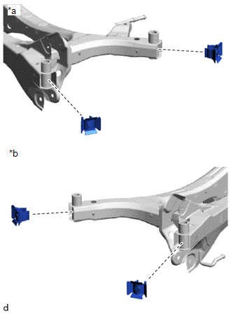
(b) Using an engine lifter and 4 attachments or equivalent tools, support the rear suspension member sub-assembly as shown in the illustration.
CAUTION:
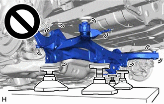
- The rear suspension member sub-assembly is a very heavy component. Make sure that it is supported securely.
- If the rear suspension member sub-assembly is not securely supported, it may drop, resulting in serious injury.
|
*a |
Engine Lifter |
|
*b |
Attachment |
.png) |
Attachment and Wooden Block Placement Location |
(c) Remove the 2 bolts and 2 nuts.
(d) Slowly lower the rear suspension member sub-assembly.
NOTICE:
When lowering the rear suspension member sub-assembly, be careful not to damage the vehicle body or other components installed to the vehicle.
20. REMOVE REAR UPPER CONTROL ARM ASSEMBLY LH
Click here
21. REMOVE REAR UPPER CONTROL ARM ASSEMBLY RH
HINT:
Perform the same procedure as for the LH side.
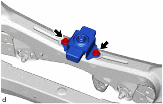
22. REMOVE REAR SUSPENSION MEMBER DAMPER
|
(a) Remove the 2 bolts and rear suspension member damper from the rear suspension member sub-assembly. |
|
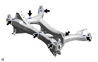
23. REMOVE REAR SUSPENSION MEMBER HOLE COVER
|
(a) Remove the 4 rear suspension member hole covers from the rear suspension member sub-assembly as shown in the illustration. |
|
24. REMOVE HOLE PLUG
|
(a) Remove the 7 hole plugs from the rear suspension member sub-assembly as shown in the illustration. |
|
 Components
COMPONENTS
ILLUSTRATION
*1
TAIL EXHAUST PIPE ASSEMBLY
*2
COMPRESSION SPRING
N*m (kgf*cm, ft.*lbf): Specified torque
...
 Installation
INSTALLATION
PROCEDURE
1. INSTALL HOLE PLUG
(a) Install the 7 hole plugs to the rear suspension member sub-assembly as shown
in the illustration.
2. INSTALL REAR SUSPENSION MEMBER HOLE COVER
(a ...
Other materials:
Toyota CH-R Service Manual > Can Communication System: Open in Bus 5 Main Bus Line
DESCRIPTION
There may be an open circuit in one of the CAN main bus lines when the resistance
between terminals 15 (CA5H) and 16 (CA5L) of the central gateway ECU (network gateway
ECU) is 70 Ω or higher.
Symptom
Trouble Area
Resistance between terminals ...
Toyota CH-R Service Manual > Outer Rear View Mirror: Removal
REMOVAL
CAUTION / NOTICE / HINT
HINT:
Use the same procedure for the RH side and LH side.
The following procedure is for the LH side.
PROCEDURE
1. REMOVE FRONT DOOR INSIDE HANDLE BEZEL PLUG
Click here
2. REMOVE MULTIPLEX NETWORK MASTER SWITCH ASSEMBLY WITH FRONT ARMRES ...
Toyota C-HR (AX20) 2023-2026 Owner's Manual
Toyota CH-R Owners Manual
- For safety and security
- Instrument cluster
- Operation of each component
- Driving
- Interior features
- Maintenance and care
- When trouble arises
- Vehicle specifications
- For owners
Toyota CH-R Service Manual
- Introduction
- Maintenance
- Audio / Video
- Cellular Communication
- Navigation / Multi Info Display
- Park Assist / Monitoring
- Brake (front)
- Brake (rear)
- Brake Control / Dynamic Control Systems
- Brake System (other)
- Parking Brake
- Axle And Differential
- Drive Shaft / Propeller Shaft
- K114 Cvt
- 3zr-fae Battery / Charging
- Networking
- Power Distribution
- Power Assist Systems
- Steering Column
- Steering Gear / Linkage
- Alignment / Handling Diagnosis
- Front Suspension
- Rear Suspension
- Tire / Wheel
- Tire Pressure Monitoring
- Door / Hatch
- Exterior Panels / Trim
- Horn
- Lighting (ext)
- Mirror (ext)
- Window / Glass
- Wiper / Washer
- Door Lock
- Heating / Air Conditioning
- Interior Panels / Trim
- Lighting (int)
- Meter / Gauge / Display
- Mirror (int)
- Power Outlets (int)
- Pre-collision
- Seat
- Seat Belt
- Supplemental Restraint Systems
- Theft Deterrent / Keyless Entry

0.0131