Toyota CH-R Service Manual: Removal
REMOVAL
PROCEDURE
1. REMOVE REAR WHEEL
Click here
.gif)
2. REMOVE REAR STABILIZER LINK ASSEMBLY LH
|
(a) Loosen the nut (A) of the rear stabilizer link assembly LH. HINT: If the ball joint turns together with the nut, use a 6 mm hexagon socket wrench to hold the stud bolt. |
|
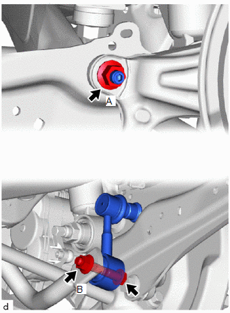
(b) Loosen the nut (B) of the rear stabilizer link assembly LH.
NOTICE:
Because the bolt has its own stopper, do not turn the bolt. Loosen the nut with the bolt secured.
|
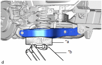
(c) Using a jack and a wooden block, support the rear No. 2 suspension arm assembly. NOTICE:
|
|
|
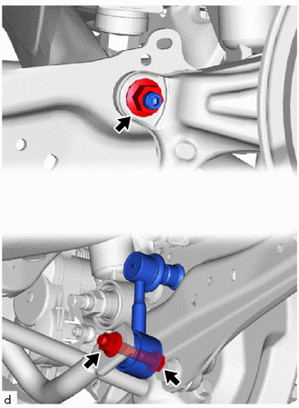
(d) Remove the bolt, 2 nuts and rear stabilizer link assembly LH. |
|
3. REMOVE REAR STABILIZER LINK ASSEMBLY RH
HINT:
Perform the same procedure as for the LH side.
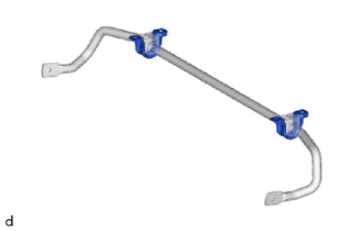
4. REMOVE REAR STABILIZER BAR
|
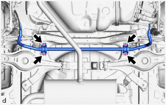
(a) Remove the 4 bolts, rear stabilizer bar, 2 rear No. 1 stabilizer bar brackets and 2 rear stabilizer bushings from the rear suspension member sub-assembly. |
|
5. REMOVE REAR NO. 1 STABILIZER BAR BRACKET
|
(a) Remove the 2 rear No. 1 stabilizer bar brackets from the 2 rear stabilizer bushings. |
|
6. REMOVE REAR STABILIZER BUSHING
|
(a) Remove the 2 rear stabilizer bushings from the rear stabilizer bar. |
|

 Components
COMPONENTS
ILLUSTRATION
*1
REAR NO. 1 STABILIZER BAR BRACKET
*2
REAR STABILIZER BAR
*3
REAR STABILIZER BUSHING
*4 ...
 Inspection
INSPECTION
PROCEDURE
1. INSPECT REAR STABILIZER LINK ASSEMBLY
(a) Inspect the turning torque of the ball joint.
(1) Secure the rear stabilizer link assembly in a vise using aluminum plates.
NOT ...
Other materials:
Toyota CH-R Service Manual > Power Window Control System: Remote Up / Down Function does not Operate
DESCRIPTION
When the ignition switch is ON, the multiplex network master switch assembly
sends remote up and down signals to each power window regulator motor assembly via
LIN communication.
WIRING DIAGRAM
CAUTION / NOTICE / HINT
NOTICE:
The power window control system uses the LI ...
Toyota CH-R Service Manual > Lighting (int): Room Light Bulb
Replacement
REPLACEMENT
PROCEDURE
1. REMOVE NO. 2 ROOM LIGHT BULB
(a) Using a screwdriver with its tip wrapped in protective tape, disengage the
claws to remove the room light lens as shown in the illustration.
*a
Protective Tape
Remove in t ...
Toyota C-HR (AX20) 2023-2026 Owner's Manual
Toyota CH-R Owners Manual
- For safety and security
- Instrument cluster
- Operation of each component
- Driving
- Interior features
- Maintenance and care
- When trouble arises
- Vehicle specifications
- For owners
Toyota CH-R Service Manual
- Introduction
- Maintenance
- Audio / Video
- Cellular Communication
- Navigation / Multi Info Display
- Park Assist / Monitoring
- Brake (front)
- Brake (rear)
- Brake Control / Dynamic Control Systems
- Brake System (other)
- Parking Brake
- Axle And Differential
- Drive Shaft / Propeller Shaft
- K114 Cvt
- 3zr-fae Battery / Charging
- Networking
- Power Distribution
- Power Assist Systems
- Steering Column
- Steering Gear / Linkage
- Alignment / Handling Diagnosis
- Front Suspension
- Rear Suspension
- Tire / Wheel
- Tire Pressure Monitoring
- Door / Hatch
- Exterior Panels / Trim
- Horn
- Lighting (ext)
- Mirror (ext)
- Window / Glass
- Wiper / Washer
- Door Lock
- Heating / Air Conditioning
- Interior Panels / Trim
- Lighting (int)
- Meter / Gauge / Display
- Mirror (int)
- Power Outlets (int)
- Pre-collision
- Seat
- Seat Belt
- Supplemental Restraint Systems
- Theft Deterrent / Keyless Entry

0.0113