Toyota CH-R Service Manual: Removal
REMOVAL
CAUTION / NOTICE / HINT
The necessary procedures (adjustment, calibration, initialization, or registration) that must be performed after parts are removed and installed, or replaced during rear coil spring removal/installation are shown below.
Necessary Procedures After Parts Removed/Installed/Replaced|
Replaced Part or Performed Procedure |
Necessary Procedure |
Effect/Inoperative Function when Necessary Procedure not Performed |
Link |
|---|---|---|---|
|
Rear wheel alignment adjustment |
|
|
|
|
Removal/installation of rear height control sensor sub-assembly LH*1 |
Initialize headlight ECU sub-assembly LH |
Automatic headlight beam level control system |
|
|
Suspension, tires, etc. (The vehicle height changes because of suspension or tire replacement)*1 |
- *1: w/ Height Control Sensor
HINT:
- Use the same procedure for the RH side and LH side.
- The following procedure is for the LH side.
PROCEDURE
1. REMOVE REAR WHEEL
Click here
.gif)
2. REMOVE REAR HEIGHT CONTROL SENSOR SUB-ASSEMBLY LH (w/ Height Control Sensor)
Click here
3. REMOVE REAR COIL SPRING
|
(a) Place matchmarks on the No. 2 camber adjust cam, rear suspension toe adjust cam sub-assembly and rear suspension member sub-assembly. |
|
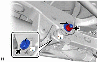
(b) Loosen the nut (rear suspension member sub-assembly side) of the rear No. 2 suspension arm assembly.
NOTICE:
Hold the rear suspension toe adjust cam sub-assembly while rotating the nut.
|
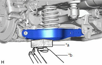
(c) Using a jack and a wooden block, support the rear No. 2 suspension arm assembly. NOTICE:
|
|
|
(d) Remove the bolt and nut, and separate the rear No. 2 suspension arm assembly (rear axle carrier sub-assembly side) from the rear axle carrier sub-assembly. NOTICE: Because the nut has its own stopper, do not turn the nut. Loosen the bolt with the nut secured. |
|
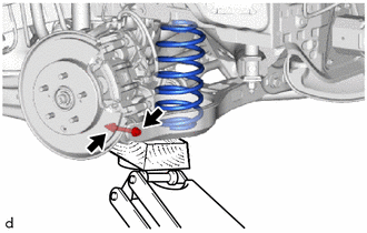
(e) Slowly lower the rear No. 2 suspension arm assembly, and then remove the rear coil spring.
4. REMOVE REAR UPPER COIL SPRING INSULATOR
(a) Remove the rear upper coil spring insulator from the vehicle.
5. REMOVE REAR LOWER COIL SPRING INSULATOR
(a) Remove the rear lower coil spring insulator from the rear No. 2 suspension arm assembly.
 Installation
INSTALLATION
CAUTION / NOTICE / HINT
HINT:
Use the same procedure for the RH side and LH side.
The following procedure is for the LH side.
PROCEDURE
1. INSTALL REAR UPPER COIL S ...
 Rear Lower Arm
...
Other materials:
Toyota CH-R Service Manual > Instrument Panel Safety Pad: Components
COMPONENTS
ILLUSTRATION
*1
COWL SIDE TRIM BOARD RH
*2
FRONT DOOR SCUFF PLATE RH
*3
GLOVE COMPARTMENT DOOR ASSEMBLY
*4
GLOVE COMPARTMENT DOOR STOPPER SUB-ASSEMBLY
*5
NO. 2 INS ...
Toyota CH-R Service Manual > Navigation System: Radio Broadcast cannot be Received or Poor Reception
WIRING DIAGRAM
for TMMT Made
for TMC Made
CAUTION / NOTICE / HINT
NOTICE:
Depending on the parts that are replaced during vehicle inspection or
maintenance, performing initialization, registration or calibration may
be needed. Refer to Precaution for Navigation System.
Cl ...
Toyota C-HR (AX20) 2023-2026 Owner's Manual
Toyota CH-R Owners Manual
- For safety and security
- Instrument cluster
- Operation of each component
- Driving
- Interior features
- Maintenance and care
- When trouble arises
- Vehicle specifications
- For owners
Toyota CH-R Service Manual
- Introduction
- Maintenance
- Audio / Video
- Cellular Communication
- Navigation / Multi Info Display
- Park Assist / Monitoring
- Brake (front)
- Brake (rear)
- Brake Control / Dynamic Control Systems
- Brake System (other)
- Parking Brake
- Axle And Differential
- Drive Shaft / Propeller Shaft
- K114 Cvt
- 3zr-fae Battery / Charging
- Networking
- Power Distribution
- Power Assist Systems
- Steering Column
- Steering Gear / Linkage
- Alignment / Handling Diagnosis
- Front Suspension
- Rear Suspension
- Tire / Wheel
- Tire Pressure Monitoring
- Door / Hatch
- Exterior Panels / Trim
- Horn
- Lighting (ext)
- Mirror (ext)
- Window / Glass
- Wiper / Washer
- Door Lock
- Heating / Air Conditioning
- Interior Panels / Trim
- Lighting (int)
- Meter / Gauge / Display
- Mirror (int)
- Power Outlets (int)
- Pre-collision
- Seat
- Seat Belt
- Supplemental Restraint Systems
- Theft Deterrent / Keyless Entry

0.0102