Toyota CH-R Service Manual: Removal
REMOVAL
CAUTION / NOTICE / HINT
The necessary procedures (adjustment, calibration, initialization, or registration) that must be performed after parts are removed and installed, or replaced during front lower ball joint assembly removal/installation are shown below.
Necessary Procedures After Parts Removed/Installed/Replaced|
Replaced Part or Performed Procedure |
Necessary Procedure |
Effect/Inoperative Function when Necessary Procedure not Performed |
Link |
|---|---|---|---|
|
Front wheel alignment adjustment |
|
|
|
HINT:
- Use the same procedure for the RH side and LH side.
- The following procedure is for the LH side.
PROCEDURE
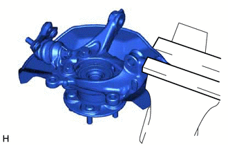
1. REMOVE FRONT AXLE ASSEMBLY
Click here
.gif)
2. REMOVE FRONT LOWER BALL JOINT ASSEMBLY
|
(a) Secure the front axle assembly in a vise using aluminum plates. NOTICE: Do not overtighten the vise. |
|
|
(b) Remove the cotter pin. |
|
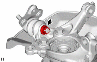
(c) Remove the nut.
|
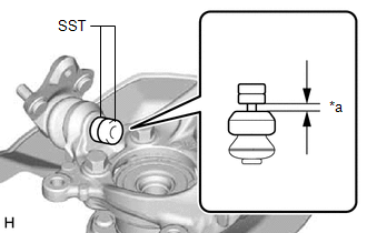
(d) Install SST to the front lower ball joint assembly as shown in the illustration. SST: 09960-20010 09961-02050 NOTICE: Check that the clearance measurement between SST and the front axle assembly is 1 mm (0.0394 in.). |
|
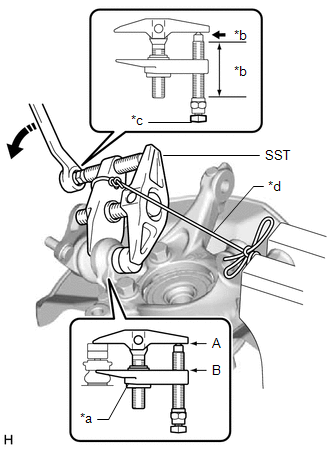
(e) Using SST, remove the front lower ball joint assembly from the front axle assembly as shown in the illustration.
SST: 09960-20010
09961-02010
09961-02050
|
*a |
Center Nut |
|
*b |
Molybdenum Grease Application Area |
|
*c |
Place wrench here |
|
*d |
String |
.png) |
Turn |
NOTICE:
- Apply molybdenum grease to the threads and end of the SST bolt.
- Install SST with the center nut so that (A) and (B) shown in the illustration are parallel. Otherwise, the front lower ball joint dust cover may be damaged.
- Be sure to place a wrench on the part shown in the illustration.
- Do not damage the front lower ball joint dust cover.
- Do not damage the steering knuckle.
- Do not damage the front disc brake dust cover.
 On-vehicle Inspection
ON-VEHICLE INSPECTION
PROCEDURE
1. INSPECT FRONT LOWER BALL JOINT ASSEMBLY
(a) Check for looseness.
(1) Lift up the vehicle.
(2) Move the front lower No. 1 suspension arm sub-assem ...
 Inspection
INSPECTION
PROCEDURE
1. INSPECT FRONT LOWER BALL JOINT ASSEMBLY
(a) Inspect the turning torque of the ball joint.
(1) Secure the front lower ball joint assembly in a vise using alumin ...
Other materials:
Toyota CH-R Service Manual > Navigation Ecu: Components
COMPONENTS
ILLUSTRATION
*1
COWL SIDE TRIM BOARD LH
*2
FRONT DOOR SCUFF PLATE LH
*3
INSTRUMENT CLUSTER FINISH LOWER CENTER PANEL SUB-ASSEMBLY
*4
INSTRUMENT CLUSTER FINISH PANEL GARNISH ASSEMBLY
...
Toyota CH-R Service Manual > Lighting System: Lost Communication With Headlamp Control Module "B" (U0242)
DESCRIPTION
The headlight ECU sub-assembly LH stores this DTC when the headlight ECU sub-assembly
RH detects an internal malfunction or if a communication malfunction occurs between
headlight ECU sub-assembly LH and headlight ECU sub-assembly RH for 10 seconds or
more.
DTC No.
...
Toyota C-HR (AX20) 2023-2026 Owner's Manual
Toyota CH-R Owners Manual
- For safety and security
- Instrument cluster
- Operation of each component
- Driving
- Interior features
- Maintenance and care
- When trouble arises
- Vehicle specifications
- For owners
Toyota CH-R Service Manual
- Introduction
- Maintenance
- Audio / Video
- Cellular Communication
- Navigation / Multi Info Display
- Park Assist / Monitoring
- Brake (front)
- Brake (rear)
- Brake Control / Dynamic Control Systems
- Brake System (other)
- Parking Brake
- Axle And Differential
- Drive Shaft / Propeller Shaft
- K114 Cvt
- 3zr-fae Battery / Charging
- Networking
- Power Distribution
- Power Assist Systems
- Steering Column
- Steering Gear / Linkage
- Alignment / Handling Diagnosis
- Front Suspension
- Rear Suspension
- Tire / Wheel
- Tire Pressure Monitoring
- Door / Hatch
- Exterior Panels / Trim
- Horn
- Lighting (ext)
- Mirror (ext)
- Window / Glass
- Wiper / Washer
- Door Lock
- Heating / Air Conditioning
- Interior Panels / Trim
- Lighting (int)
- Meter / Gauge / Display
- Mirror (int)
- Power Outlets (int)
- Pre-collision
- Seat
- Seat Belt
- Supplemental Restraint Systems
- Theft Deterrent / Keyless Entry

0.0116