Toyota CH-R Service Manual: Parts Location
PARTS LOCATION
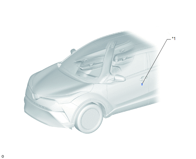
ILLUSTRATION
|
*1 |
FRONT DOOR COURTESY LIGHT SWITCH ASSEMBLY LH |
- |
- |
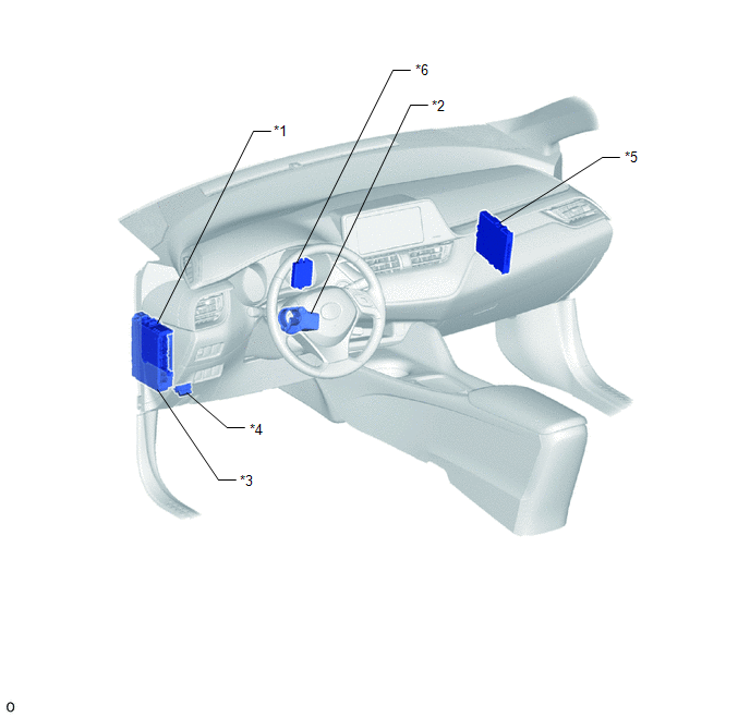
ILLUSTRATION
|
*1 |
MAIN BODY ECU (MULTIPLEX NETWORK BODY ECU) |
*2 |
STEERING LOCK ECU (STEERING LOCK ACTUATOR OR UPPER BRACKET ASSEMBLY) |
|
*3 |
INSTRUMENT PANEL JUNCTION BLOCK ASSEMBLY - IG2-NO. 2 RELAY - STRG LOCK FUSE - ECU-IG2 NO. 3 FUSE |
*4 |
DLC3 |
|
*5 |
CERTIFICATION ECU (SMART KEY ECU ASSEMBLY) |
*6 |
ID CODE BOX (IMMOBILISER CODE ECU) |
 Precaution
PRECAUTION
PRECAUTIONS WHEN CHECKING FOR DTCS
(a) When the cable is disconnected from the negative (-) battery terminal, the
DTCs stored in the steering lock ECU (steering lock actuator or upper b ...
 System Description
SYSTEM DESCRIPTION
UNLOCK OPERATION CONDITIONS FOR STEERING LOCK
(a) When the following condition is met, the unlock operation is performed.
The engine switch is on (ACC) or on (IG).
HINT ...
Other materials:
Toyota CH-R Service Manual > Windshield Outside Moulding: Installation
INSTALLATION
CAUTION / NOTICE / HINT
HINT:
Use the same procedure for the RH side and LH side.
The following procedure is for the LH side.
PROCEDURE
1. INSTALL NO. 3 WINDSHIELD OUTSIDE MOULDING CLIP
HINT:
Perform the following procedure only when replacement of a No. 3 winds ...
Toyota CH-R Service Manual > Transponder Key Ecu: Installation
INSTALLATION
CAUTION / NOTICE / HINT
NOTICE:
Before replacing the transponder key ECU assembly, refer to Registration.
Click here
PROCEDURE
1. INSTALL TRANSPONDER KEY ECU ASSEMBLY
(a) Engage the guides to install the transponder key ECU assembly as shown in
the illustration.
...
Toyota C-HR (AX20) 2023-2026 Owner's Manual
Toyota CH-R Owners Manual
- For safety and security
- Instrument cluster
- Operation of each component
- Driving
- Interior features
- Maintenance and care
- When trouble arises
- Vehicle specifications
- For owners
Toyota CH-R Service Manual
- Introduction
- Maintenance
- Audio / Video
- Cellular Communication
- Navigation / Multi Info Display
- Park Assist / Monitoring
- Brake (front)
- Brake (rear)
- Brake Control / Dynamic Control Systems
- Brake System (other)
- Parking Brake
- Axle And Differential
- Drive Shaft / Propeller Shaft
- K114 Cvt
- 3zr-fae Battery / Charging
- Networking
- Power Distribution
- Power Assist Systems
- Steering Column
- Steering Gear / Linkage
- Alignment / Handling Diagnosis
- Front Suspension
- Rear Suspension
- Tire / Wheel
- Tire Pressure Monitoring
- Door / Hatch
- Exterior Panels / Trim
- Horn
- Lighting (ext)
- Mirror (ext)
- Window / Glass
- Wiper / Washer
- Door Lock
- Heating / Air Conditioning
- Interior Panels / Trim
- Lighting (int)
- Meter / Gauge / Display
- Mirror (int)
- Power Outlets (int)
- Pre-collision
- Seat
- Seat Belt
- Supplemental Restraint Systems
- Theft Deterrent / Keyless Entry

0.0108