Toyota CH-R Service Manual: TC and CG Terminal Circuit
DESCRIPTION
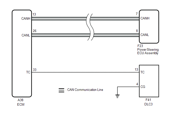
Connecting terminals TC and CG of the DLC3 causes the ECU to display DTCs by blinking the EPS warning light.
WIRING DIAGRAM
CAUTION / NOTICE / HINT
NOTICE:
If the power steering ECU assembly has been replaced, perform assist map writing and torque sensor zero point calibration.
Click here
.gif)
HINT:
When the warning lights continue to blink, a ground short in the wiring of terminal TC of the DLC3 or an internal ground short in one or more ECUs is suspected.
PROCEDURE
|
1. |
CHECK CAN COMMUNICATION SYSTEM |
(a) Check for DTCs.
Click here
|
Result |
Proceed to |
|---|---|
|
CAN communication system DTCs are not output. |
A |
|
CAN communication system DTCs are output. |
B |
| B | .gif) |
GO TO CAN COMMUNICATION SYSTEM
|
|
.gif)
|
2. |
INSPECT DLC3 |
|
(a) Turn the ignition switch to ON. |
|
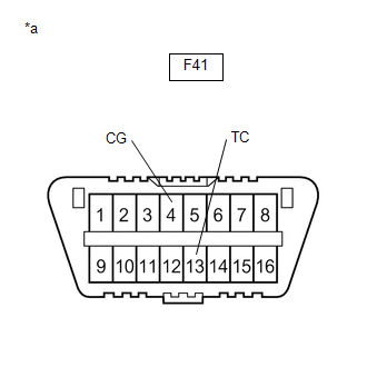
(b) Measure the voltage according to the value(s) in the table below.
Standard Voltage:
|
Tester Connection |
Condition |
Specified Condition |
|---|---|---|
|
F41-13 (TC) - F41-4 (CG) |
Ignition switch ON |
9 to 16 V |
| NG | |
GO TO STEP 4 |
|
|
3. |
REPLACE ECU |
|
(a) Turn the ignition switch off. |
|
(b) Replace the ECM.
Click here
(c) Using SST, connect terminals TC and CG of the DLC3.
SST: 09843-18040
(d) Check that the EPS warning light is blinking.
OK:
The EPS warning light is blinking.
HINT:
If troubleshooting has been carried out according to Problem Symptoms Table, refer back to the table and proceed to the next step before replacing the part.
Click here
| OK | |
END |
| NG | |
REPLACE POWER STEERING ECU ASSEMBLY |
|
4. |
CHECK HARNESS AND CONNECTOR (TC of DLC3 - ECM) |
(a) Disconnect the A38 ECM connector.
(b) Measure the resistance according to the value(s) in the table below.
Standard Resistance:
|
Tester Connection |
Condition |
Specified Condition |
|---|---|---|
|
F41-13 (TC) - A38-33 (TC) |
Always |
Below 1 Ω |
|
F41-13 (TC) or A38-33 (TC) - Body ground |
Always |
10 kΩ or higher |
| NG | |
REPAIR OR REPLACE HARNESS OR CONNECTOR |
|
|
5. |
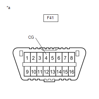
CHECK HARNESS AND CONNECTOR (CG of DLC3 - BODY GROUND) |
|
(a) Measure the resistance according to the value(s) in the table below. Standard Resistance:
HINT: If troubleshooting has been carried out according to Problem Symptoms Table, refer back to the table and proceed to the next step before replacing the part. Click here
|
|
| NG | |
REPAIR OR REPLACE HARNESS OR CONNECTOR OR EACH ECU |
|
|
6. |
REPLACE ECU |
|
(a) Replace the ECM. |
|
(b) Using SST, connect terminals TC and CG of the DLC3.
Click here
SST: 09843-18040
(c) Check that the EPS warning light is blinking.
OK:
The EPS warning light is blinking.
HINT:
If troubleshooting has been carried out according to Problem Symptoms Table, refer back to the table and proceed to the next step before replacing the part.
Click here
| OK | |
END |
| NG | |
REPLACE POWER STEERING ECU ASSEMBLY |
 Lost Communication With ECM/PCM "A" (U0100,U0129,U023A)
DESCRIPTION
The power steering ECU assembly receives signals from the ECM and skid control
ECU (brake actuator assembly) via CAN communication.
DTC No.
Detection Item
...
 Steering Column
...
Other materials:
Toyota CH-R Service Manual > Airbag System: How To Proceed With Troubleshooting
CAUTION / NOTICE / HINT
HINT:
Use the following procedure to troubleshoot the airbag system.
*: Use the Techstream.
PROCEDURE
1.
VEHICLE BROUGHT TO WORKSHOP
NEXT
2.
...
Toyota CH-R Service Manual > Safety Connect System: Telematics Transceiver Malfunction (B15A8)
DESCRIPTION
This DTC is set when an error in the EEPROM or PLL IC is detected on the DCM
(Telematics Transceiver) self-check. The EEPROM (Electrically Erasable Programmable
Read-Only Memory) stores the various data to operate the safety connect system.
The PLL IC (Phase-Locked Loop Integrated ...
Toyota C-HR (AX20) 2023-2026 Owner's Manual
Toyota CH-R Owners Manual
- For safety and security
- Instrument cluster
- Operation of each component
- Driving
- Interior features
- Maintenance and care
- When trouble arises
- Vehicle specifications
- For owners
Toyota CH-R Service Manual
- Introduction
- Maintenance
- Audio / Video
- Cellular Communication
- Navigation / Multi Info Display
- Park Assist / Monitoring
- Brake (front)
- Brake (rear)
- Brake Control / Dynamic Control Systems
- Brake System (other)
- Parking Brake
- Axle And Differential
- Drive Shaft / Propeller Shaft
- K114 Cvt
- 3zr-fae Battery / Charging
- Networking
- Power Distribution
- Power Assist Systems
- Steering Column
- Steering Gear / Linkage
- Alignment / Handling Diagnosis
- Front Suspension
- Rear Suspension
- Tire / Wheel
- Tire Pressure Monitoring
- Door / Hatch
- Exterior Panels / Trim
- Horn
- Lighting (ext)
- Mirror (ext)
- Window / Glass
- Wiper / Washer
- Door Lock
- Heating / Air Conditioning
- Interior Panels / Trim
- Lighting (int)
- Meter / Gauge / Display
- Mirror (int)
- Power Outlets (int)
- Pre-collision
- Seat
- Seat Belt
- Supplemental Restraint Systems
- Theft Deterrent / Keyless Entry

0.0094