Toyota CH-R Service Manual: Terminals Of Ecu
TERMINALS OF ECU
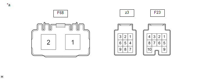
CHECK POWER STEERING ECU ASSEMBLY
|
*a |
Component without harness connected (Power Steering ECU Assembly) |
- |
- |
(a) Measure the voltage and resistance according to the value(s) in the table below.
NOTICE:
When the EPS warning light is illuminated due to a malfunction, the fail-safe function may cause the voltage of the power steering ECU assembly terminals to become 0 V.
|
Terminal No. (Symbol) |
Wiring Color |
Terminal Description |
Condition |
Specified Condition |
|---|---|---|---|---|
|
F23-1 (IG) - Body ground |
LG - Body ground |
IG power source |
Ignition switch ON |
8 to 16 V |
|
F23-7 (CANH) - F23-8 (CANL) |
P - W |
CAN communication line |
Ignition switch off |
54 to 69 Ω |
|
z3-1 (TRQ2) - z3-2 (TRQG2) |
Y - G |
Torque sensor 2 signal |
Engine running and steering wheel not being turned (without load) |
2.3 to 2.7 V |
|
Engine running and steering wheel being turned to the right with vehicle stopped |
1.2 to 2.5 V |
|||
|
Engine running and steering wheel being turned to the left with vehicle stopped |
2.5 to 3.8 V |
|||
|
z3-2 (TRQG2) - Body ground |
G - Body ground |
Torque sensor 2 ground |
Always |
Below 1 Ω |
|
z3-3 (TRQV2) - z3-2 (TRQG2) |
L - G |
Torque sensor 2 voltage source |
Ignition switch ON |
4.5 to 5.5 V |
|
z3-7 (TRQV1) - z3-8 (TRQG1) |
R - B |
Torque sensor 1 voltage source |
Ignition switch ON |
4.5 to 5.5 V |
|
z3-8 (TRQG1) - Body ground |
B - Body ground |
Torque sensor 1 ground |
Always |
Below 1 Ω |
|
z3-9 (TRQ1) - z3-8 (TRQG1) |
W - B |
Torque sensor signal |
Engine running and steering wheel not being turned (without load) |
2.3 to 2.7 V |
|
Engine running and steering wheel being turned to the right with vehicle stopped |
2.5 to 3.8 V |
|||
|
Engine running and steering wheel being turned to the left with vehicle stopped |
1.2 to 2.5 V |
|||
|
F68-1 (PIG) - Body ground |
B-W - Body ground |
Power source |
Ignition switch ON |
9 to 16 V |
|
F68-2 (PGND) - Body ground |
W-B - Body ground |
Power ground |
Always |
Below 1 Ω |
If the result is not as specified, the ECU may be malfunctioning.
 Diagnosis System
DIAGNOSIS SYSTEM
CHECK DLC3
(a) Check the DLC3.
Click here
CHECK WARNING LIGHT
(a) When a problem occurs in the power steering system, the EPS warning light
in the combination meter assembl ...
 Dtc Check / Clear
DTC CHECK / CLEAR
CHECK DTCs (USING TECHSTREAM)
(a) Turn the ignition switch off.
(b) Connect the Techstream to the DLC3.
(c) Turn the ignition switch to ON.
(d) Turn the Techstream on.
(e) Ente ...
Other materials:
Toyota CH-R Service Manual > Audio And Visual System(for Radio And Display Type): No Sound can be Heard from Speakers
PROCEDURE
1.
CHECK AUDIO SETTINGS
(a) In sound output setting mode, set volume, fader and balance to the initial
values and check that the sound is normal.
OK:
Audio system returns to normal.
HINT:
Sound quality adjustment measures vary according to the type ...
Toyota CH-R Service Manual > Heating / Air Conditioning: Air Conditioning Panel
Components
COMPONENTS
ILLUSTRATION
*1
AIR CONDITIONING CONTROL ASSEMBLY
*2
INSTRUMENT CLUSTER FINISH LOWER CENTER PANEL SUB-ASSEMBLY
*3
INSTRUMENT CLUSTER FINISH PANEL GARNISH ASSEMBLY
-
-
...
Toyota C-HR (AX20) 2023-2026 Owner's Manual
Toyota CH-R Owners Manual
- For safety and security
- Instrument cluster
- Operation of each component
- Driving
- Interior features
- Maintenance and care
- When trouble arises
- Vehicle specifications
- For owners
Toyota CH-R Service Manual
- Introduction
- Maintenance
- Audio / Video
- Cellular Communication
- Navigation / Multi Info Display
- Park Assist / Monitoring
- Brake (front)
- Brake (rear)
- Brake Control / Dynamic Control Systems
- Brake System (other)
- Parking Brake
- Axle And Differential
- Drive Shaft / Propeller Shaft
- K114 Cvt
- 3zr-fae Battery / Charging
- Networking
- Power Distribution
- Power Assist Systems
- Steering Column
- Steering Gear / Linkage
- Alignment / Handling Diagnosis
- Front Suspension
- Rear Suspension
- Tire / Wheel
- Tire Pressure Monitoring
- Door / Hatch
- Exterior Panels / Trim
- Horn
- Lighting (ext)
- Mirror (ext)
- Window / Glass
- Wiper / Washer
- Door Lock
- Heating / Air Conditioning
- Interior Panels / Trim
- Lighting (int)
- Meter / Gauge / Display
- Mirror (int)
- Power Outlets (int)
- Pre-collision
- Seat
- Seat Belt
- Supplemental Restraint Systems
- Theft Deterrent / Keyless Entry

0.0101