Toyota CH-R Service Manual: Acceleration Sensor Circuit (P1585)
DESCRIPTION
The ECM determines the vehicle inclination based on a signal from the airbag sensor assembly (yaw rate and acceleration sensor). If a malfunction in the airbag sensor assembly (yaw rate and acceleration sensor) is determined based on a malfunction signal from the skid control ECU (brake actuator assembly), the ECM stores this DTC.
HINT:
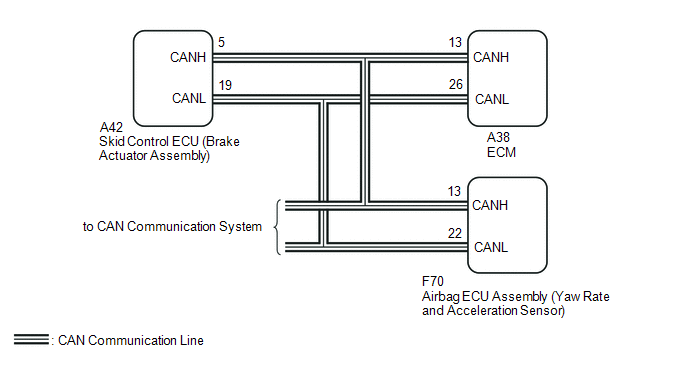
- The airbag sensor assembly (yaw rate and acceleration sensor) signal is sent to the skid control ECU (brake actuator assembly) via CAN communication.
- If CAN communication DTCs are output, perform troubleshooting for those DTCs first.
|
DTC No. |
Detection Item |
DTC Detection Condition |
Trouble Area |
MIL |
Memory |
|---|---|---|---|---|---|
|
P1585 |
Acceleration Sensor Circuit |
After the ignition switch is turned ON, the skid control ECU (brake actuator assembly) has detected one of the following conditions, and the ECM has received a diagnostic signal from the skid control ECU (brake actuator assembly) for 3 seconds or more (1 trip detection logic).
|
|
Does not come on |
DTC stored |
|
Vehicle Condition |
||||||
|---|---|---|---|---|---|---|
|
Pattern 1 |
Pattern 2 |
Pattern 3 |
Pattern 4 |
Pattern 5 |
||
|
Diagnostic Condition |
The ignition switch is ON. |
○ |
○ |
○ |
○ |
○ |
|
Malfunction Condition |
The output value of the airbag sensor assembly (yaw rate and acceleration sensor) remains at -1.5 G or less, or 1.5 G or more for at least 1.2 seconds or more. |
○ |
- |
- |
- |
- |
|
The airbag sensor assembly (yaw rate and acceleration sensor) power source voltage is at 4.4 V or less, or 5.6 V or higher for 1.2 seconds or more. |
- |
○ |
- |
- |
- |
|
|
No signal from the airbag sensor assembly (yaw rate and acceleration sensor) is detected 7 times or more. |
- |
- |
○ |
- |
- |
|
|
With the vehicle stopped, the difference between GL1 and GL2 does not become less than 0.4 G within 60 seconds after exceeding 0.6 G. |
- |
- |
- |
○ |
- |
|
|
An airbag sensor assembly (yaw rate and acceleration sensor) power source voltage malfunction signal is received for at least 10 seconds with the vehicle speed at 3 km/h (1.8 mph) or more. |
- |
- |
- |
- |
○ |
|
|
Duration |
3 seconds or more |
3 seconds or more |
3 seconds or more |
3 seconds or more |
3 seconds or more |
|
|
Detection Logic |
1 trip detection logic |
1 trip detection logic |
1 trip detection logic |
1 trip detection logic |
1 trip detection logic |
|
HINT:
This DTC is output when any one of the above detection patterns is met.
WIRING DIAGRAM
CAUTION / NOTICE / HINT
NOTICE:
- Perform initialization after replacing any parts related to the continuously
variable transaxle system.
Click here
.gif)
- Check that no DTCs are stored after performing initialization.
Click here
HINT:
After performing repair, clear the DTCs and perform the following procedure to check that DTCs are not output.
- Turn the ignition switch to ON and wait for 60 seconds or more.
- Perform the D Position Shift Test inspection in Road Test.
Click here
- Check for DTCs again.
Click here
PROCEDURE
|
1. |
CHECK DTC OUTPUT |
(a) Connect the Techstream to the DLC3.
(b) Turn the ignition switch to ON.
(c) Turn the Techstream on.
(d) Check for DTCs.
Powertrain > Engine and ECT > Trouble Codes|
Result |
Proceed to |
|---|---|
|
DTC U0129 is not output |
A |
|
DTC U0129 is output |
B |
| B | .gif) |
GO TO CAN COMMUNICATION SYSTEM
|
|
.gif)
|
2. |
READ VALUE USING TECHSTREAM (G SENSOR) |
(a) Connect the Techstream to the DLC3.
(b) Turn the ignition switch to ON.
(c) Turn the Techstream on.
(d) Enter the following menus: Powertrain / Engine and ECT / Data List.
Powertrain > Engine and ECT > Data List|
Tester Display |
|---|
|
G Sensor |
(e) In accordance with the display on the Techstream, read the Data List.
Powertrain > Engine and ECT > Data List|
Tester Display |
Measurement Item |
Range |
Normal Condition |
Diagnostic Note |
|---|---|---|---|---|
|
G Sensor |
Converted output voltage of yaw rate and acceleration sensor |
Min.: 0 V Max.: 79.998 V |
Displays converted voltage of yaw rate and acceleration sensor
|
- |
|
Result |
Proceed to |
|---|---|
|
Data display is not within Normal Condition range |
A |
|
Data display is within Normal Condition range |
B |
| B | |
REPLACE BRAKE ACTUATOR ASSEMBLY |
|
|
3. |
REPLACE AIRBAG SENSOR ASSEMBLY |
(a) Replace the airbag sensor assembly (yaw rate and acceleration sensor).
Click here
| NEXT | |
PERFORM INITIALIZATION |
 Torque Converter Clutch Circuit Performance or Stuck OFF (P0741,P075B,P2757)
DESCRIPTION
The ECM uses the shift solenoid valves SC and SL to switch control of the shift
solenoid valve SLU between forward and reverse clutch control and lock-up control
in response to drivin ...
 Acceleration Sensor Malfunction (P1586)
DESCRIPTION
The ECM determines the vehicle inclination based on a signal from the airbag
sensor assembly (yaw rate and acceleration sensor). If a malfunction of the airbag
sensor assembly (yaw ra ...
Other materials:
Toyota CH-R Service Manual > Window / Glass: Power Window Master Switch
Components
COMPONENTS
ILLUSTRATION
*1
MULTIPLEX NETWORK MASTER SWITCH ASSEMBLY
*2
MULTIPLEX NETWORK MASTER SWITCH ASSEMBLY WITH FRONT ARMREST BASE UPPER
PANEL
*3
FRONT DOOR UPPER ARMREST BASE PANEL
-
...
Toyota CH-R Service Manual > Charging System: Freeze Frame Data
FREEZE FRAME DATA
DESCRIPTION
The ECM records vehicle and driving condition information as freeze frame data
the moment a DTC is stored. When troubleshooting, freeze frame data can be helpful
in determining whether the vehicle was moving or stationary, whether the engine
was warmed up or not ...
Toyota C-HR (AX20) 2023-2026 Owner's Manual
Toyota CH-R Owners Manual
- For safety and security
- Instrument cluster
- Operation of each component
- Driving
- Interior features
- Maintenance and care
- When trouble arises
- Vehicle specifications
- For owners
Toyota CH-R Service Manual
- Introduction
- Maintenance
- Audio / Video
- Cellular Communication
- Navigation / Multi Info Display
- Park Assist / Monitoring
- Brake (front)
- Brake (rear)
- Brake Control / Dynamic Control Systems
- Brake System (other)
- Parking Brake
- Axle And Differential
- Drive Shaft / Propeller Shaft
- K114 Cvt
- 3zr-fae Battery / Charging
- Networking
- Power Distribution
- Power Assist Systems
- Steering Column
- Steering Gear / Linkage
- Alignment / Handling Diagnosis
- Front Suspension
- Rear Suspension
- Tire / Wheel
- Tire Pressure Monitoring
- Door / Hatch
- Exterior Panels / Trim
- Horn
- Lighting (ext)
- Mirror (ext)
- Window / Glass
- Wiper / Washer
- Door Lock
- Heating / Air Conditioning
- Interior Panels / Trim
- Lighting (int)
- Meter / Gauge / Display
- Mirror (int)
- Power Outlets (int)
- Pre-collision
- Seat
- Seat Belt
- Supplemental Restraint Systems
- Theft Deterrent / Keyless Entry

0.0159