Toyota CH-R Service Manual: High Temperature Adjustment
HIGH TEMPERATURE ADJUSTMENT
CAUTION / NOTICE / HINT
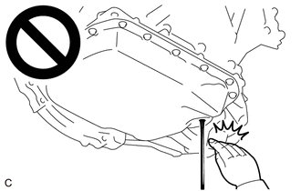
CAUTION:
- Be careful not to burn yourself when the fluid temperature is high.
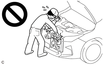
- To prevent injury due to contact with an operating V-ribbed belt or
cooling fan, keep your hands and clothing away from the V-ribbed belt and
cooling fans when working in the engine compartment with the engine running
or the ignition switch ON.
PROCEDURE
1. ADJUST FLUID LEVEL CVT HIGH TEMPERATURE
(a) Warm up and stop the engine.
(b) Check the fluid temperature.
(1) Connect the Techstream to the DLC3 with the ignition switch off.
(2) Turn the ignition switch ON and turn the Techstream on.
NOTICE:
To reduce load, make sure that all electrical systems, such as the air conditioning, lighting system, electric fan and audio system, are off.
(3) Enter the following menus: Powertrain / Engine and ECT / Data List / Engine Speed, A/T Oil Temperature 1.
Powertrain > Engine and ECT > Data List|
Tester Display |
|---|
|
Engine Speed |
|
A/T Oil Temperature 1 |
NOTICE:
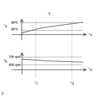
- If the fluid temperature tends to decrease when the fluid temperature is between 85°C (185°F) and 90°C (194°F) with the engine idling, make sure that fluid temperature is above 90°C (194°F) before starting work.
- If the fluid temperature tends to increase when the fluid temperature is between 85°C (185°F) and 90°C (194°F) with the engine idling, make sure that fluid temperature is below 85°C (185°F) before starting work.
- If the fluid temperature tends to not change when the fluid temperature is between 85°C (185°F) and 90°C (194°F) with the engine idling, make sure that fluid temperature is 87.5°C (189.5°F) before starting work.
(c) Depress and hold the brake pedal.
(d) Start the engine.
(e) Slowly move the shift lever from P to D, and then back to P (keep the shift lever in each position for approximately 3 seconds).
HINT:
Slowly move the shift lever to circulate the fluid through each part of the continuously variable transaxle assembly.
(f) Lift the vehicle.
NOTICE:
Set the vehicle on a lift so that the vehicle is kept level when it is lifted up (make sure the tilt angle from the front to rear of the vehicle is within +/-1°).
(g) Remove the No. 1 engine under cover.
Click here
.gif)
(h) Remove the rear engine under cover LH.
Click here
|
(i) Loosen the refill plug. |
|
.png)
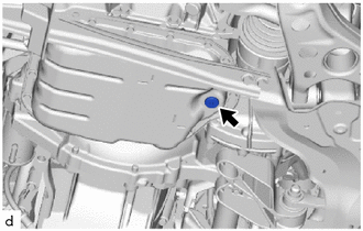
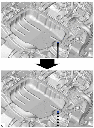
(j) Using a 6 mm hexagon socket wrench, remove the overflow plug and gasket from the transaxle oil (CVT) pan sub-assembly, and drain the fluid. [*1]
CAUTION:
Be careful as the fluid coming out of the overflow plug hole is hot.
NOTICE:
- Before removing the overflow plug, make sure that the fluid temperature is between 85°C (185°F) and 90°C (194°F) and the engine idle speed is within the range specified in the tables provided in step [*3].
- When adding fluid (step [*3]), add the specified amount in accordance with the engine idle speed.
- If fluid does not come out, install the overflow plug, add fluid to the refill hole until fluid comes out, and perform the procedure from step [*1] again.
|
(1) Make sure that the fluid temperature and engine idle speed remain within the appropriate range until the overflow plug is tightened in step [*2]. |
|
|
(k) Wait until the fluid flow slows and only drips come out. HINT: If the fluid temperature is increasing, the fluid flow will not completely stop because the fluid expands as its temperature increases. |
|
|
(l) Using a 6 mm hexagon socket wrench, install a new gasket and the overflow plug to the transaxle oil (CVT) pan sub-assembly. [*2] Torque: 40 N·m {408 kgf·cm, 30 ft·lbf} |
|
(m) Lower the vehicle.
(n) Turn the ignition switch off.
|
(o) Remove the refill plug and gasket from the continuously variable transaxle assembly. |
|
|
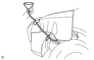
(p) Install a hose and funnel to the refill hole as shown in the illustration. NOTICE:
HINT: Make sure to use a hose with a length of 1250 mm (4.1 ft.) and an outer diameter of 16 mm (0.63 in.). |
|
(q) Add the specified amount of fluid to the refill hole. [*3]
(1) If determining the specific amount of fluid to be added, refer to the table below.
Specified Amount to be Added:
|
Engine Idle Speed (rpm) |
Specified Amount to be Added at Fluid Temperature of 85°C (185°F) to 90°C (194°F) |
|---|---|
|
550 to 850 |
250 g (8.8 oz.) (300 cc (18.3 cu in.)) |
NOTICE:
- If fluid remains inside the hose, the amount of fluid will be outside the specification. Therefore, when adding fluid, make sure that no fluid remains inside the hose.
- The acceptable margin of error when adding fluid is +/-20 g (0.7 oz.).
- Use Toyota Genuine CVT fluid FE.
HINT:
- The values in the table are reference values for when the temperature of the fluid to be added is between 10°C (50°F) and 30°C (86°F).
- If fluid comes out (the amount of fluid is not as specified), perform the procedure from step [*1] again.
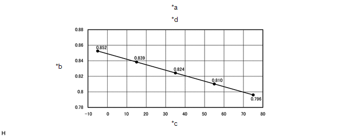
(2) If determining the specified amount of fluid to be added by volume, calculate it based on weight and density at each temperature.
|
*a |
This example shows the volume of fluid to be added with a fluid temperature of 10°C (50°F) to 30°C (86°F). |
*b |
Density [g/cc] |
|
*c |
Temperature of fluid to be measured [°C ] |
*d |
Relation between temperature and density of Toyota Genuine CVT fluid FE |
(r) Install a new gasket and the refill plug to the continuously variable transaxle assembly.
Torque:
49 N·m {500 kgf·cm, 36 ft·lbf}
(s) Disconnect the Techstream from the DLC3.
2. REBUILD WORK
(a) Lift the vehicle.
(b) Clean each part.
(c) Check for fluid leaks.
(d) Install the rear engine under cover LH.
Click here
(e) Install the No. 1 engine under cover.
Click here
(f) Lower the vehicle.
 Components
COMPONENTS
ILLUSTRATION
*1
REFILL PLUG
*2
OVERFLOW PLUG
*3
NO. 1 TRANSMISSION OIL FILLER TUBE
*4
DRAIN ...
 Replacement
REPLACEMENT
CAUTION / NOTICE / HINT
Click here
...
Other materials:
Toyota CH-R Service Manual > Wiper / Washer: Front Wiper Rubber
Components
COMPONENTS
ILLUSTRATION
*1
FRONT WIPER BLADE
*2
WIPER RUBBER
...
Toyota CH-R Service Manual > Rain Sensor: Components
COMPONENTS
ILLUSTRATION
*1
RAIN SENSOR
*2
RAIN SENSOR COVER
*3
RAIN SENSOR TAPE
-
-
...
Toyota C-HR (AX20) 2023-2026 Owner's Manual
Toyota CH-R Owners Manual
- For safety and security
- Instrument cluster
- Operation of each component
- Driving
- Interior features
- Maintenance and care
- When trouble arises
- Vehicle specifications
- For owners
Toyota CH-R Service Manual
- Introduction
- Maintenance
- Audio / Video
- Cellular Communication
- Navigation / Multi Info Display
- Park Assist / Monitoring
- Brake (front)
- Brake (rear)
- Brake Control / Dynamic Control Systems
- Brake System (other)
- Parking Brake
- Axle And Differential
- Drive Shaft / Propeller Shaft
- K114 Cvt
- 3zr-fae Battery / Charging
- Networking
- Power Distribution
- Power Assist Systems
- Steering Column
- Steering Gear / Linkage
- Alignment / Handling Diagnosis
- Front Suspension
- Rear Suspension
- Tire / Wheel
- Tire Pressure Monitoring
- Door / Hatch
- Exterior Panels / Trim
- Horn
- Lighting (ext)
- Mirror (ext)
- Window / Glass
- Wiper / Washer
- Door Lock
- Heating / Air Conditioning
- Interior Panels / Trim
- Lighting (int)
- Meter / Gauge / Display
- Mirror (int)
- Power Outlets (int)
- Pre-collision
- Seat
- Seat Belt
- Supplemental Restraint Systems
- Theft Deterrent / Keyless Entry

0.0086