Toyota CH-R Service Manual: Operation Method
OPERATION METHOD
PROCEDURE
1. PRECAUTION
Click here
.gif)
2. REMOVE DECK BOARD ASSEMBLY
Click here
3. REMOVE SPARE WHEEL CUSHION
Click here
4. REMOVE DECK FLOOR BOX LH
Click here
5. REMOVE DECK FLOOR BOX RH
Click here
6. PARKING BRAKE FORCED RELEASE
CAUTION:
Work on a level surface to ensure safety.
NOTICE:
- To release the parking brake, follow the procedure for when using SST.
- If the parking brake cannot be released, follow the procedure for when not using SST.
- When moving the vehicle after releasing the parking brake, install all
parts except the connector shown in the illustration.
- If the ignition switch ON or the engine is started with the connector
disconnected, a DTC may be stored. Clear any DTCs after performing work.
Click here
(a) When using SST:
(1) Park the vehicle on a level surface and move the shift lever to P.
(2) Turn the ignition switch off and chock the wheels.
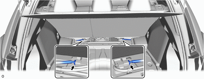
(3) Disconnect the connector shown in the illustration.
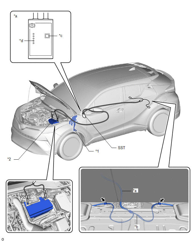
(4) Connect SST (09756-48020) to SST (09756-48070).
SST: 09756-48020
SST: 09756-48070
|
*1 |
Brake Pedal Support Assembly |
*2 |
Battery |
|
*a |
SST(09756-48020) |
*b |
SST(09756-48070) |
|
*c |
Release Button |
*d |
Finished Light |
.png) |
Connector |
- |
- |
(5) Connect SST (09756-48070) to the connector inside of the vehicle.
(6) Connect SST (09756-48020) to the battery from the outside of the vehicle.
(7) Push the release button on SST (09756-48020) with the brake pedal depressed.
CAUTION:
The vehicle may suddenly move when the parking brake is released. Make sure to perform the release operation with the brake pedal depressed.
HINT:
- Confirm that the parking brake is operating by listening for operation sounds.
- If no operation sounds are heard, push the release button on SST with the brake pedal depressed.
- The parking brake may not release if the battery voltage is too low. In this case, perform the release operation again using a fully charged or new battery.
(8) When the FINISHED light of SST (09756-48020) illuminates, release the brake pedal.
(9) Move the vehicle forward and rearward to check that the parking brake is released.
CAUTION:
Be careful when performing this operation. The vehicle may suddenly move.
NOTICE:
- When moving the vehicle after releasing the parking brake, check that the connector is disconnected.
- The brake warning light (yellow) will illuminate when the vehicle is moved after releasing the parking brake.
(b) When not using SST:
NOTICE:
Perform the following procedure only when the parking brake cannot be released using SST.
HINT:
- Use the same procedure for the RH side and LH side.
- The following procedure is for the LH side.
(1) Park the vehicle on a level surface and check that the shift lever is in P.
(2) Turn the ignition switch off and check that the wheels are chocked.
(3) Check that the connector shown in the illustration has been disconnected.
(4) Remove the rear wheel.
Click here
CAUTION:
When using a jack, do not work on a vehicle supported only by jacks. Make sure to use safety stands.
Click here
|
(5) Disconnect the No. 2 parking brake wire assembly connector from the parking brake actuator assembly. |
|
.png)
(6) Remove the parking brake actuator assembly from the rear disc brake cylinder assembly.
Click here
|
(7) Insert a 6 mm hexagon wrench into the rear disc brake cylinder assembly. |
|
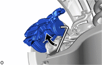
(8) Turn the 6 mm hexagon wrench 2 turns clockwise to release the parking brake lock.
NOTICE:
- When moving the vehicle after releasing the parking brake, install all
parts except the connector shown in the illustration.
- The brake warning light (yellow) will illuminate when the vehicle is moved after releasing the parking brake.
7. INSTALL DECK FLOOR BOX LH
Click here
8. INSTALL DECK FLOOR BOX RH
Click here
9. INSTALL SPARE WHEEL CUSHION
Click here
10. INSTALL DECK BOARD ASSEMBLY
Click here


Other materials:
Toyota CH-R Service Manual > Audio And Visual System(for Radio And Display Type): Portable Player cannot be Operated Using In-vehicle Device or Track Information
is not Displayed on In-vehicle Device
PROCEDURE
1.
CHECK USING ANOTHER "Bluetooth" AUDIO COMPATIBLE VEHICLE OF SAME MODEL
(a) Check if track information is displayed normally on another "Bluetooth" audio
compatible vehicle of the same model.
OK:
Track information is displayed no ...
Toyota CH-R Service Manual > Wheel Opening Moulding(for Rear): Disassembly
DISASSEMBLY
CAUTION / NOTICE / HINT
HINT:
Use the same procedure for the RH and LH sides.
The procedure listed below is for the LH side.
PROCEDURE
1. REMOVE NO. 1 BODY OUTSIDE MOULDING PAD
(a) Remove the No. 1 body outside moulding pad (double-sided tape).
HINT:
Do not pu ...
Toyota C-HR (AX20) 2023-2026 Owner's Manual
Toyota CH-R Owners Manual
- For safety and security
- Instrument cluster
- Operation of each component
- Driving
- Interior features
- Maintenance and care
- When trouble arises
- Vehicle specifications
- For owners
Toyota CH-R Service Manual
- Introduction
- Maintenance
- Audio / Video
- Cellular Communication
- Navigation / Multi Info Display
- Park Assist / Monitoring
- Brake (front)
- Brake (rear)
- Brake Control / Dynamic Control Systems
- Brake System (other)
- Parking Brake
- Axle And Differential
- Drive Shaft / Propeller Shaft
- K114 Cvt
- 3zr-fae Battery / Charging
- Networking
- Power Distribution
- Power Assist Systems
- Steering Column
- Steering Gear / Linkage
- Alignment / Handling Diagnosis
- Front Suspension
- Rear Suspension
- Tire / Wheel
- Tire Pressure Monitoring
- Door / Hatch
- Exterior Panels / Trim
- Horn
- Lighting (ext)
- Mirror (ext)
- Window / Glass
- Wiper / Washer
- Door Lock
- Heating / Air Conditioning
- Interior Panels / Trim
- Lighting (int)
- Meter / Gauge / Display
- Mirror (int)
- Power Outlets (int)
- Pre-collision
- Seat
- Seat Belt
- Supplemental Restraint Systems
- Theft Deterrent / Keyless Entry

0.0094