Toyota CH-R Service Manual: Removal
REMOVAL
CAUTION / NOTICE / HINT
HINT:
- Use the same procedure for the RH side and LH side.
- The following procedure is for the LH side.
PROCEDURE
1. PRECAUTION
Click here
.gif)
2. REMOVE REAR WHEEL
Click here
3. PERFORM REAR BRAKE PAD REPLACEMENT MODE
Click here
4. DRAIN BRAKE FLUID
NOTICE:
If brake fluid leaks onto any painted surface, immediately wash it off.
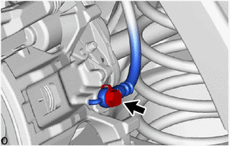
5. SEPARATE REAR FLEXIBLE HOSE
|
(a) Remove the union bolt and gasket, and disconnect the rear flexible hose from the rear disc brake cylinder assembly. |
|
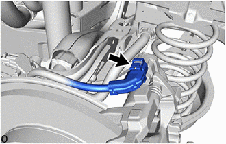
6. DISCONNECT NO. 2 PARKING BRAKE WIRE ASSEMBLY
|
(a) Disconnect the No. 2 parking brake wire assembly from the parking brake actuator assembly. NOTICE:
|
|
7. REMOVE PARKING BRAKE ACTUATOR ASSEMBLY
|
(a) Using a 5 mm hexagon socket wrench, remove the 2 bolts and parking brake actuator assembly from the rear disc brake cylinder assembly. NOTICE:
|
|
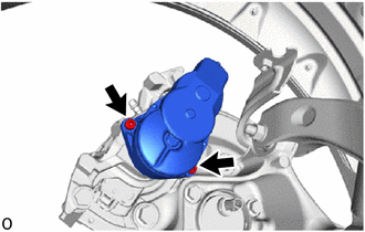
(b) Remove the O-ring from the rear disc brake cylinder assembly.
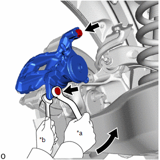
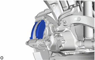
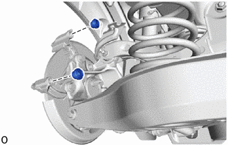
8. REMOVE REAR DISC BRAKE CYLINDER ASSEMBLY
|
(a) Hold the 2 rear disc brake cylinder slide pins and remove the 2 bolts and rear disc brake cylinder assembly. |
|
9. REMOVE REAR DISC BRAKE PAD
|
(a) Remove the 2 rear disc brake pads from the rear disc brake cylinder mounting. |
|
10. REMOVE REAR DISC BRAKE ANTI-SQUEAL SHIM KIT
Click here
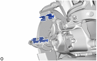
11. REMOVE REAR DISC BRAKE PAD SUPPORT PLATE
|
(a) Remove the 4 rear disc brake pad support plates from the rear disc brake cylinder mounting. NOTICE: Each rear disc brake pad support plate has a different shape. Be sure to put an identification mark on each rear disc brake pad support plate so that it can be reinstalled to its original position. |
|
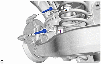
12. REMOVE REAR DISC BRAKE CYLINDER SLIDE PIN
|
(a) Remove the rear No. 1 disc brake cylinder slide pin and rear No. 2 disc brake cylinder slide pin from the rear disc brake cylinder mounting. |
|
|
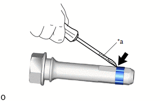
(b) Using a screwdriver with its tip wrapped with protective tape, remove the rear disc brake cylinder slide bushing from the rear No. 2 disc brake cylinder slide pin. NOTICE: Do not damage the rear No. 2 disc brake cylinder slide pin. |
|
13. REMOVE REAR DISC BRAKE BUSHING DUST BOOT
|
(a) Remove the 2 rear disc brake bushing dust boots from the rear disc brake cylinder mounting. |
|
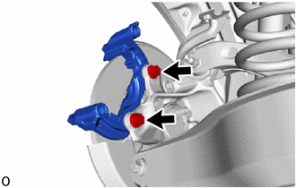
14. REMOVE REAR DISC BRAKE CYLINDER MOUNTING
|
(a) Remove the 2 bolts and rear disc brake cylinder mounting from the rear axle carrier sub-assembly. |
|
15. REMOVE REAR DISC
|
(a) Put matchmarks on the rear disc and rear axle hub and bearing assembly. |
|
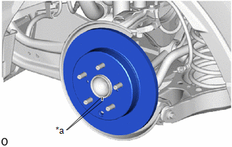
(b) Remove the rear disc from the rear axle hub and bearing assembly.
 Disassembly
DISASSEMBLY
CAUTION / NOTICE / HINT
NOTICE:
If the rear disc brake cylinder assembly has been disassembled, perform
air bleeding for the rear disc brake cylinder.
Click here
...
 Inspection
INSPECTION
PROCEDURE
1. INSPECT PAD LINING THICKNESS
(a) Using a ruler, measure the rear disc brake pad lining thickness.
Standard Thickness:
9.5 mm (0.374 in.)
Minimum Thickne ...
Other materials:
Toyota CH-R Service Manual > Rear View Monitor System: System Description
SYSTEM DESCRIPTION
GENERAL
(a) This system has a rear television camera assembly mounted on the back door
to assist the driver in parking the vehicle by displaying an image of the area behind
the vehicle. The system displays the image on the multi-display.
(b) This system consists of the foll ...
Toyota CH-R Service Manual > Blind Spot Monitor System: Lost Communication with Blind Spot Monitor Slave Module (U0232)
DESCRIPTION
This DTC is stored when the blind spot monitor sensor LH (Master) judges that
there is a communication problem with the blind spot monitor sensor RH (Slave).
DTC No.
Detection Item
DTC Detection Condition
Trouble Area
U0232 ...
Toyota C-HR (AX20) 2023-2026 Owner's Manual
Toyota CH-R Owners Manual
- For safety and security
- Instrument cluster
- Operation of each component
- Driving
- Interior features
- Maintenance and care
- When trouble arises
- Vehicle specifications
- For owners
Toyota CH-R Service Manual
- Introduction
- Maintenance
- Audio / Video
- Cellular Communication
- Navigation / Multi Info Display
- Park Assist / Monitoring
- Brake (front)
- Brake (rear)
- Brake Control / Dynamic Control Systems
- Brake System (other)
- Parking Brake
- Axle And Differential
- Drive Shaft / Propeller Shaft
- K114 Cvt
- 3zr-fae Battery / Charging
- Networking
- Power Distribution
- Power Assist Systems
- Steering Column
- Steering Gear / Linkage
- Alignment / Handling Diagnosis
- Front Suspension
- Rear Suspension
- Tire / Wheel
- Tire Pressure Monitoring
- Door / Hatch
- Exterior Panels / Trim
- Horn
- Lighting (ext)
- Mirror (ext)
- Window / Glass
- Wiper / Washer
- Door Lock
- Heating / Air Conditioning
- Interior Panels / Trim
- Lighting (int)
- Meter / Gauge / Display
- Mirror (int)
- Power Outlets (int)
- Pre-collision
- Seat
- Seat Belt
- Supplemental Restraint Systems
- Theft Deterrent / Keyless Entry

0.0091