Toyota CH-R Service Manual: Blind Spot Monitor Sensor
Components
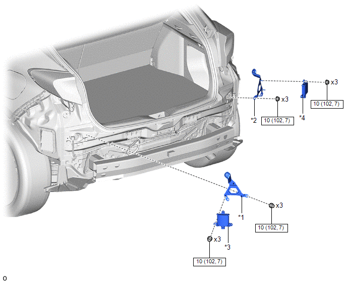
COMPONENTS
ILLUSTRATION
|
*1 |
BLIND SPOT MONITOR BRACKET LH |
*2 |
BLIND SPOT MONITOR BRACKET RH |
|
*3 |
BLIND SPOT MONITOR SENSOR LH |
*4 |
BLIND SPOT MONITOR SENSOR RH |
.png) |
N*m (kgf*cm, ft.*lbf): Specified torque |
- |
- |
Installation
INSTALLATION
CAUTION / NOTICE / HINT
NOTICE:
- Avoid any impact to the blind spot monitor sensor.
- Do not drop the blind spot monitor sensor. If it is dropped, replace it with a new one.
HINT:
- The blind spot monitor beam axis inspection is performed to confirm whether the sensor is transmitting radio waves.
- The blind spot monitor beam axis confirmation is performed to confirm whether the sensor's beam axis is correct, and perform adjustment of the beam axis by using reflector.
- The blind spot monitor sensor installation condition inspection is performed to confirm whether the sensor is placed vertically to the ground (+/-5°) by using a jig, and that the sensor is 16 to 24° from the line parallel to the vehicle center line.
PROCEDURE
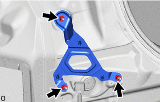
1. INSTALL BLIND SPOT MONITOR BRACKET LH
(a) Install the blind spot monitor sensor bracket LH with the 3 nuts.
Torque:
10 N·m {102 kgf·cm, 7 ft·lbf}
2. INSTALL BLIND SPOT MONITOR BRACKET RH
HINT:
Use the same procedure as for the LH side.
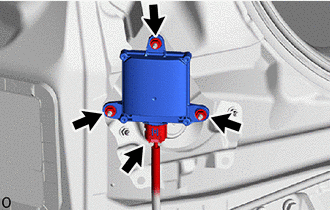
3. INSTALL BLIND SPOT MONITOR SENSOR LH
(a) Connect the connector.
(b) Install the blind spot monitor LH with the 3 nuts.
Torque:
10 N·m {102 kgf·cm, 7 ft·lbf}
4. INSTALL BLIND SPOT MONITOR SENSOR RH
HINT:
Use the same procedure as for the LH side.
5. PERFORM BLIND SPOT MONITOR SENSOR INSTALLATION CONDITION INSPECTION
Click here
.gif)
6. INSTALL REAR BUMPER ASSEMBLY
Click here
7. PERFORM BLIND SPOT MONITOR BEAM AXIS CONFIRMATION
Click here
SST: 09870-60000
09870-60010
SST: 09870-60040
8. PERFORM DIAGNOSTIC SYSTEM CHECK
Click here
Removal
REMOVAL
CAUTION / NOTICE / HINT
The necessary procedures (adjustment, calibration, initialization, or registration) that must be performed after parts are removed and installed, or replaced during the blind spot monitor sensor removal/installation are shown below.
Necessary Procedure After Parts Removed/Installed/Replaced|
Replaced Part or Performed Procedure |
Necessary Procedure |
Effect/Inoperative Function when Necessary Procedure not Performed |
Link |
|---|---|---|---|
|
Replacement of blind spot monitor sensor |
Blind Spot Monitor Beam Axis Adjustment |
DTCs are output |
|
PROCEDURE
1. REMOVE REAR BUMPER ASSEMBLY
Click here
.gif)
2. REMOVE BLIND SPOT MONITOR SENSOR LH
|
(a) Disconnect the connector. |
|
(b) Remove the 3 nuts and blind spot monitor sensor LH.
NOTICE:
Replace the blind spot monitor sensor LH if it has been dropped or subjected to a severe impact.
3. REMOVE BLIND SPOT MONITOR SENSOR RH
HINT:
Use the same procedure as for the LH side.
4. REMOVE BLIND SPOT MONITOR BRACKET LH
|
(a) Remove the 3 nuts and blind spot monitor bracket LH. |
|
5. REMOVE BLIND SPOT MONITOR BRACKET RH
HINT:
Use the same procedure as for the LH side.


Other materials:
Toyota CH-R Service Manual > Airbag System: Front Airbag Sensor RH Malfunction (B1610/13)
DESCRIPTION
The front airbag sensor RH circuit consists of the airbag sensor assembly and
front airbag sensor RH.
The front airbag sensor RH detects impacts to the vehicle and sends signals to
the airbag sensor assembly to determine if the airbags and pretensioners should
be deployed.
DTC B ...
Toyota CH-R Service Manual > Headlight Assembly(for Led Headlight): Installation
INSTALLATION
CAUTION / NOTICE / HINT
HINT:
Use the same procedure for the RH side and LH side.
The following procedure is for the LH side.
PROCEDURE
1. INSTALL HEADLIGHT ASSEMBLY
(a) Temporarily install the headlight assembly as shown in the illustration.
...
Toyota C-HR (AX20) 2023-2026 Owner's Manual
Toyota CH-R Owners Manual
- For safety and security
- Instrument cluster
- Operation of each component
- Driving
- Interior features
- Maintenance and care
- When trouble arises
- Vehicle specifications
- For owners
Toyota CH-R Service Manual
- Introduction
- Maintenance
- Audio / Video
- Cellular Communication
- Navigation / Multi Info Display
- Park Assist / Monitoring
- Brake (front)
- Brake (rear)
- Brake Control / Dynamic Control Systems
- Brake System (other)
- Parking Brake
- Axle And Differential
- Drive Shaft / Propeller Shaft
- K114 Cvt
- 3zr-fae Battery / Charging
- Networking
- Power Distribution
- Power Assist Systems
- Steering Column
- Steering Gear / Linkage
- Alignment / Handling Diagnosis
- Front Suspension
- Rear Suspension
- Tire / Wheel
- Tire Pressure Monitoring
- Door / Hatch
- Exterior Panels / Trim
- Horn
- Lighting (ext)
- Mirror (ext)
- Window / Glass
- Wiper / Washer
- Door Lock
- Heating / Air Conditioning
- Interior Panels / Trim
- Lighting (int)
- Meter / Gauge / Display
- Mirror (int)
- Power Outlets (int)
- Pre-collision
- Seat
- Seat Belt
- Supplemental Restraint Systems
- Theft Deterrent / Keyless Entry

0.0074