Toyota CH-R Service Manual: GVIF Disconnected (from Extension Module to H/U) (B153A)
DESCRIPTION
|
DTC No. |
Detection Item |
DTC Detection Condition |
Trouble Area |
|---|---|---|---|
|
B153A |
GVIF Disconnected (from Extension Module to H/U) |
GVIF disconnected (from navigation ECU to radio and display receiver assembly) |
|
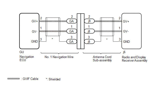
WIRING DIAGRAM
CAUTION / NOTICE / HINT
NOTICE:
- Depending on the parts that are replaced during vehicle inspection or
maintenance, performing initialization, registration or calibration may
be needed. Refer to Precaution for Navigation System.
Click here
.gif)
- When replacing the radio and display receiver assembly or navigation
ECU, always replace it with a new one. If a radio and display receiver assembly
or navigation ECU which was installed to another vehicle is used, the following
may occur:
- A communication malfunction DTC may be stored.
- The radio and display receiver assembly or navigation ECU may not operate normally.
PROCEDURE
|
1. |
CHECK DTC |
(a) Clear the DTCs.
Body Electrical > Navigation System > Clear DTCs(b) Recheck for DTCs and check that no DTCs are output.
Body Electrical > Navigation System > Trouble CodesOK:
No DTCs are output.
| OK | .gif) |
USE SIMULATION METHOD TO CHECK |
|
.gif)
|
2. |
INSPECT NO. 1 NAVIGATION WIRE |
|
(a) Disconnect the GA No. 1 navigation wire connector from the antenna cord sub-assembly. |
|
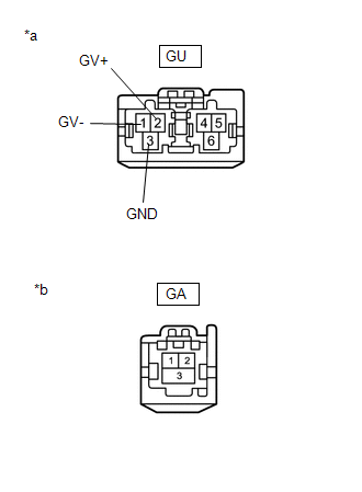
(b) Disconnect the GU No. 1 navigation wire connector from the navigation ECU.
(c) Measure the resistance according to the value(s) in the table below.
Standard Resistance:
|
Tester Connection |
Condition |
Specified Condition |
|---|---|---|
|
GU-1 (GV-) - GA-1 |
Always |
Below 1 Ω |
|
GU-2 (GV+) - GA-2 |
Always |
Below 1 Ω |
|
GU-3 (GND) - GA-3 |
Always |
Below 1 Ω |
| NG | |
REPAIR OR REPLACE HARNESS OR CONNECTOR |
|
|
3. |
REPLACE ANTENNA CORD SUB-ASSEMBLY |
(a) Replace the antenna cord sub-assembly with a new or known good one.
Click here
|
|
4. |
CHECK DTC |
(a) Clear the DTCs.
Body Electrical > Navigation System > Clear DTCs(b) Recheck for DTCs and check that no DTCs are output.
Body Electrical > Navigation System > Trouble CodesOK:
No DTCs are output.
| OK | |
END (ANTENNA CORD SUB-ASSEMBLY IS DEFECTIVE) |
|
|
5. |
REPLACE NAVIGATION ECU |
(a) Replace the navigation ECU with a new one.
Click here
|
|
6. |
CHECK DTC |
(a) Clear the DTCs.
Body Electrical > Navigation System > Clear DTCs(b) Recheck for DTCs and check that no DTCs are output.
Body Electrical > Navigation System > Trouble CodesOK:
No DTCs are output.
| OK | |
END (NAVIGATION ECU IS DEFECTIVE) |
| NG | |
REPLACE RADIO AND DISPLAY RECEIVER ASSEMBLY |
 Lost Communication with Meter (B1324)
DESCRIPTION
This DTC is stored when a communication error occurs between the radio and display
receiver assembly and combination meter assembly.
DTC No.
Detection Item
...
 Satellite Radio Broadcast cannot be Received
CAUTION / NOTICE / HINT
NOTICE:
Some satellite radio broadcasts require payment. A contract must be made between
a satellite radio company and the user. If the contract expires, it will not be
p ...
Other materials:
Toyota CH-R Service Manual > Continuously Variable Transaxle Fluid: Components
COMPONENTS
ILLUSTRATION
*1
REFILL PLUG
*2
OVERFLOW PLUG
*3
NO. 1 TRANSMISSION OIL FILLER TUBE
*4
DRAIN PLUG
*5
NO. 1 ENGINE UNDER COVER
*6
REAR ENGINE U ...
Toyota CH-R Service Manual > Electric Parking Brake System: Freeze Frame Data
FREEZE FRAME DATA
FREEZE FRAME DATA
HINT:
When a DTC is stored, the freeze frame data stores the current vehicle
(sensor) state as.
The freeze frame data cannot be cleared or updated until the recorded
DTCs are cleared.
Chassis > ABS/VSC/TRAC/EPB
Tester D ...
Toyota C-HR (AX20) 2023-2026 Owner's Manual
Toyota CH-R Owners Manual
- For safety and security
- Instrument cluster
- Operation of each component
- Driving
- Interior features
- Maintenance and care
- When trouble arises
- Vehicle specifications
- For owners
Toyota CH-R Service Manual
- Introduction
- Maintenance
- Audio / Video
- Cellular Communication
- Navigation / Multi Info Display
- Park Assist / Monitoring
- Brake (front)
- Brake (rear)
- Brake Control / Dynamic Control Systems
- Brake System (other)
- Parking Brake
- Axle And Differential
- Drive Shaft / Propeller Shaft
- K114 Cvt
- 3zr-fae Battery / Charging
- Networking
- Power Distribution
- Power Assist Systems
- Steering Column
- Steering Gear / Linkage
- Alignment / Handling Diagnosis
- Front Suspension
- Rear Suspension
- Tire / Wheel
- Tire Pressure Monitoring
- Door / Hatch
- Exterior Panels / Trim
- Horn
- Lighting (ext)
- Mirror (ext)
- Window / Glass
- Wiper / Washer
- Door Lock
- Heating / Air Conditioning
- Interior Panels / Trim
- Lighting (int)
- Meter / Gauge / Display
- Mirror (int)
- Power Outlets (int)
- Pre-collision
- Seat
- Seat Belt
- Supplemental Restraint Systems
- Theft Deterrent / Keyless Entry

0.0093