Toyota CH-R Service Manual: Open in Ion Generator Circuit (B14B9)
DESCRIPTION
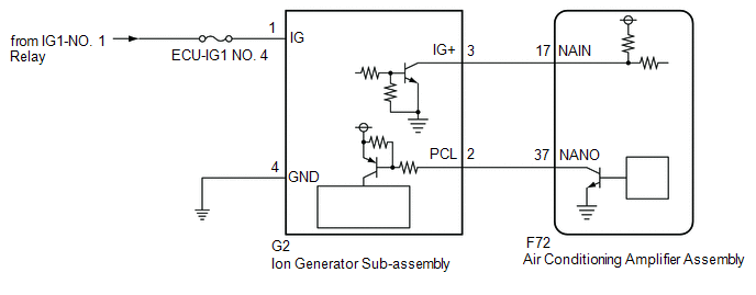
The ion generator sub-assembly operates when both the ion generator switch and the blower switch are on. The air conditioning amplifier assembly sends a drive signal to the ion generator sub-assembly. When the ion generator sub-assembly receives the drive signal and starts to operate, it outputs an operation condition signal to the air conditioning amplifier assembly.
|
DTC No. |
Detection Item |
DTC Detection Condition |
Trouble Area |
Memory |
|---|---|---|---|---|
|
B14B9 |
Open in Ion Generator Circuit |
Open in ion generator sub-assembly circuit |
|
Memorized (12 seconds or more)* |
- *: The air conditioning amplifier assembly stores this DTC if the malfunction has occurred for the period of time indicated in the brackets.
WIRING DIAGRAM
CAUTION / NOTICE / HINT
NOTICE:
Inspect the fuses for circuits related to this system before performing the following procedure.
PROCEDURE
|
1. |
PERFORM ACTIVE TEST USING TECHSTREAM (ION GENERATOR) |
(a) Connect the Techstream to the DLC3.
(b) Turn the ignition switch ON.
(c) Turn the Techstream on.
(d) Enter the following menus: Body Electrical / Air Conditioner / Active Test.
(e) Perform the Active Test according to the display on the Techstream.
Body Electrical > Air Conditioner > Active Test|
Tester Display |
Measurement Item |
Control Range |
Diagnostic Note |
|---|---|---|---|
|
Ion Generator |
Ion generator sub-assembly |
OFF or ON |
- |
|
Tester Display |
|---|
|
Ion Generator |
OK:
Ion generator sub-assembly operates normally.
|
Result |
Proceed to |
|---|---|
|
NG |
A |
|
OK (When troubleshooting according to Problem Symptoms Table) |
B |
|
OK (When troubleshooting according to the DTC) |
C |
| B | .gif) |
PROCEED TO NEXT SUSPECTED AREA SHOWN IN PROBLEM SYMPTOMS TABLE |
| C | |
GO TO STEP 6 |
|
.gif)
|
2. |
CHECK HARNESS AND CONNECTOR (ION GENERATOR SUB-ASSEMBLY - POWER SOURCE) |
|
(a) Disconnect the ion generator sub-assembly connector. |
|
(b) Measure the voltage according to the value(s) in the table below.
Standard Voltage:
|
Tester Connection |
Switch Condition |
Specified Condition |
|---|---|---|
|
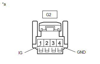
G2-1 (IG) -Body ground |
Ignition switch ON |
11 to 14 V |
|
G2-1 (IG) -Body ground |
Ignition switch off |
Below 1 V |
(c) Measure the resistance according to the value(s) in the table below.
Standard Resistance:
|
Tester Connection |
Condition |
Specified Condition |
|---|---|---|
|
G2-4 (GND) - Body ground |
Always |
Below 1 Ω |
| NG | |
REPAIR OR REPLACE HARNESS OR CONNECTOR |
|
|
3. |
CHECK HARNESS AND CONNECTOR (ION GENERATOR SUB-ASSEMBLY - AIR CONDITIONING AMPLIFIER ASSEMBLY) |
(a) Disconnect the F72 air conditioning amplifier assembly connector.
(b) Measure the resistance according to the value(s) in the table below.
Standard Resistance:
|
Tester Connection |
Condition |
Specified Condition |
|---|---|---|
|
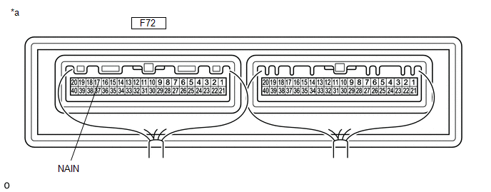
F72-17 (NAIN) - G2-3 (IG+) |
Always |
Below 1 Ω |
|
F72-37 (NANO) - G2-2 (PCL) |
Always |
Below 1 Ω |
|
F72-17 (NAIN) or G2-3 (IG+) - Body ground |
Always |
10 kΩ or higher |
|
F72-37 (NANO) or G2-2 (PCL) - Body ground |
Always |
10 kΩ or higher |
| NG | |
REPAIR OR REPLACE HARNESS AND CONNECTOR |
|
|
4. |
CHECK AIR CONDITIONING AMPLIFIER ASSEMBLY COMMUNICATION POWER SUPPLY |
(a) Reconnect the F72 air conditioning amplifier assembly connector.
(b) Measure the voltage according to the value(s) in the table below.
Standard Voltage:
|
Tester Connection |
Switch Condition |
Specified Condition |
|---|---|---|
|
G2-3 (IG+) - Body ground |
|
3.5 to 5 V |
| NG | |
REPLACE AIR CONDITIONING AMPLIFIER ASSEMBLY |
|
|
5. |
CHECK ION GENERATOR SUB-ASSEMBLY OUTPUT |
(a) Reconnect the G2 ion generator sub-assembly connector.
(b) Measure the voltage according to the value(s) in the table below.
|
*a |
Component with harness connected (Air Conditioning Amplifier Assembly) |
- |
- |
Standard Voltage:
|
Tester Connection |
Switch Condition |
Specified Condition |
|---|---|---|
|
F72-17 (NAIN) - Body ground |
|
Below 2 V |
| OK | |
REPLACE AIR CONDITIONING AMPLIFIER ASSEMBLY |
| NG | |
REPLACE ION GENERATOR SUB-ASSEMBLY |
|
6. |
CHECK FOR DTC |
(a) Clear the DTCs.
Click here
.gif)
(b) Check for DTCs.
Click here
|
Result |
Proceed to |
|---|---|
|
DTCs are not output |
A |
|
DTCs are output |
B |
| A | |
USE SIMULATION METHOD TO CHECK |
| B | |
REPLACE AIR CONDITIONING AMPLIFIER ASSEMBLY |
 Diagnostic Trouble Code Chart
DIAGNOSTIC TROUBLE CODE CHART
AIR CONDITIONING SYSTEM
DTC No.
Detection Item
DTC Detection Condition
Link
B1411
Room Temperatu ...
 Lost Communication with ECM (U0100-U0142,U0155)
DESCRIPTION
DTC No.
Detection Item
DTC Detection Condition
Trouble Area
Memory
U0100
Lost Communication with ECM
...
Other materials:
Toyota CH-R Service Manual > Washer Level Warning Switch: Inspection
INSPECTION
PROCEDURE
1. INSPECT LEVEL WARNING SWITCH ASSEMBLY
HINT:
This check should be performed with the level warning switch assembly installed
on the washer jar.
(a) Fill the washer jar with washer fluid.
...
Toyota CH-R Service Manual > Front Lower Suspension Arm: Components
COMPONENTS
ILLUSTRATION
*1
NO. 1 ENGINE UNDER COVER
*2
REAR ENGINE UNDER COVER LH
N*m (kgf*cm, ft.*lbf): Specified torque
-
-
ILLUSTRATION
*1
FRONT LOWER NO. 1 SUSPENSIO ...
Toyota C-HR (AX20) 2023-2026 Owner's Manual
Toyota CH-R Owners Manual
- For safety and security
- Instrument cluster
- Operation of each component
- Driving
- Interior features
- Maintenance and care
- When trouble arises
- Vehicle specifications
- For owners
Toyota CH-R Service Manual
- Introduction
- Maintenance
- Audio / Video
- Cellular Communication
- Navigation / Multi Info Display
- Park Assist / Monitoring
- Brake (front)
- Brake (rear)
- Brake Control / Dynamic Control Systems
- Brake System (other)
- Parking Brake
- Axle And Differential
- Drive Shaft / Propeller Shaft
- K114 Cvt
- 3zr-fae Battery / Charging
- Networking
- Power Distribution
- Power Assist Systems
- Steering Column
- Steering Gear / Linkage
- Alignment / Handling Diagnosis
- Front Suspension
- Rear Suspension
- Tire / Wheel
- Tire Pressure Monitoring
- Door / Hatch
- Exterior Panels / Trim
- Horn
- Lighting (ext)
- Mirror (ext)
- Window / Glass
- Wiper / Washer
- Door Lock
- Heating / Air Conditioning
- Interior Panels / Trim
- Lighting (int)
- Meter / Gauge / Display
- Mirror (int)
- Power Outlets (int)
- Pre-collision
- Seat
- Seat Belt
- Supplemental Restraint Systems
- Theft Deterrent / Keyless Entry

0.0099