Toyota CH-R Service Manual: AV Signal Stoppage (Low Battery Voltage) (B158F)
DESCRIPTION
This DTC is stored when a video or audio signal is interrupted due to battery voltage input to the radio and display receiver assembly dropping temporarily.
|
DTC No. |
Detection Item |
DTC Detection Condition |
Trouble Area |
|---|---|---|---|
|
B158F |
AV Signal Stoppage (Low Battery Voltage) |
A video or audio signal is interrupted when the battery voltage drops |
|
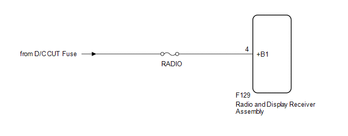
WIRING DIAGRAM
CAUTION / NOTICE / HINT
NOTICE:
- Depending on the parts that are replaced during vehicle inspection or
maintenance, performing initialization, registration or calibration may
be needed. Refer to Precaution for Navigation System.
Click here
.gif)
- When replacing the radio and display receiver assembly, always replace
it with a new one. If a radio and display receiver assembly which was installed
to another vehicle is used, the following may occur:
- A communication malfunction DTC is stored.
- The radio and display receiver assembly may not operate normally.
- Inspect the fuses for circuits related to this system before performing the following procedure.
PROCEDURE
|
1. |
CHECK VEHICLE SIGNAL (OPERATION CHECK) |
|
(a) Enter the "Vehicle Signal Check Mode" screen. Refer to Check Vehicle Signal in Operation Check. Click here
|
|
.png)
(b) Measure the battery voltage.
Standard Voltage:
11 to 14 V
HINT:
This display is updated once per second.
| NG | .gif) |
GO TO STEP 3 |
|
.gif)
|
2. |
CHECK DTC |
(a) Clear the DTCs.
Body Electrical > Navigation System > Clear DTCs(b) Recheck for DTCs and check that no DTCs are output.
Body Electrical > Navigation System > Trouble CodesOK:
No DTCs are output.
| OK | |
END |
| NG | |
REPLACE RADIO AND DISPLAY RECEIVER ASSEMBLY |
|
3. |
CHECK HARNESS AND CONNECTOR (RADIO AND DISPLAY RECEIVER ASSEMBLY POWER SOURCE) |
|
(a) Disconnect the radio and display receiver assembly connector. |
|
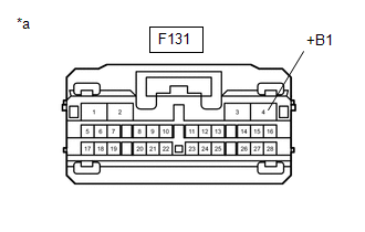
(b) Measure the voltage according to the value(s) in the table below.
Standard Voltage:
|
Tester Connection |
Condition |
Specified Condition |
|---|---|---|
|
F131-4 (+B1) - Body ground |
Always |
11 to 14 V |
| OK | |
REPLACE RADIO AND DISPLAY RECEIVER ASSEMBLY |
| NG | |
REPAIR OR REPLACE HARNESS OR CONNECTOR |
 Navigation Processor Malfunction (B15AD)
DESCRIPTION
These DTCs are stored when a malfunction occurs in the navigation ECU.
DTC No.
Detection Item
DTC Detection Condition
Trouble Area
...
 USB Device Malfunction (B1585)
DESCRIPTION
This DTC is stored when a malfunction occurs in a connected device.
DTC No.
Detection Item
DTC Detection Condition
Trouble Area
...
Other materials:
Toyota CH-R Service Manual > Door / Hatch: Rear Door Opening Trim Weatherstrip
Components
COMPONENTS
ILLUSTRATION
*A
w/o Rear Seat Side Airbag
*B
w/ Rear Seat Side Airbag
*1
REAR DOOR OPENING TRIM WEATHERSTRIP
*2
REAR DOOR SCUFF PLATE
Removal
REMOVAL
CAUTION / NOT ...
Toyota CH-R Service Manual > Integration Relay: Installation
INSTALLATION
PROCEDURE
1. INSTALL NO. 1 INTEGRATION RELAY
(a) Connect the 2 connectors.
(b) Engage the claws to install the No. 1 integration relay as shown in the illustration.
Install in this Direction
2. INSTALL NO. 1 RELAY BLOCK COVER
(a) Engage the claws to ...
Toyota CH-R Owners Manual
- For safety and security
- Instrument cluster
- Operation of each component
- Driving
- Interior features
- Maintenance and care
- When trouble arises
- Vehicle specifications
- For owners
Toyota CH-R Service Manual
- Introduction
- Maintenance
- Audio / Video
- Cellular Communication
- Navigation / Multi Info Display
- Park Assist / Monitoring
- Brake (front)
- Brake (rear)
- Brake Control / Dynamic Control Systems
- Brake System (other)
- Parking Brake
- Axle And Differential
- Drive Shaft / Propeller Shaft
- K114 Cvt
- 3zr-fae Battery / Charging
- Networking
- Power Distribution
- Power Assist Systems
- Steering Column
- Steering Gear / Linkage
- Alignment / Handling Diagnosis
- Front Suspension
- Rear Suspension
- Tire / Wheel
- Tire Pressure Monitoring
- Door / Hatch
- Exterior Panels / Trim
- Horn
- Lighting (ext)
- Mirror (ext)
- Window / Glass
- Wiper / Washer
- Door Lock
- Heating / Air Conditioning
- Interior Panels / Trim
- Lighting (int)
- Meter / Gauge / Display
- Mirror (int)
- Power Outlets (int)
- Pre-collision
- Seat
- Seat Belt
- Supplemental Restraint Systems
- Theft Deterrent / Keyless Entry

0.0157