Toyota CH-R Service Manual: Terminals Of Ecu
TERMINALS OF ECU
HINT:
Check from the rear of the connector while it is connected to the components.
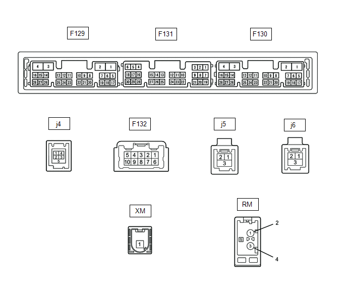
RADIO AND DISPLAY RECEIVER ASSEMBLY
|
Terminal No. (Symbol) |
Wiring Color |
Terminal Description |
Condition |
Specified Condition |
|---|---|---|---|---|
|
F132-1 (FR+) - F129-1 (GND1) |
LA-LG - LA |
Sound signal (Front right) |
Audio system playing |
A waveform synchronized with sound signals is output |
|
F132-2 (FL+) - F129-1 (GND1) |
W - LA |
Sound signal (Front left) |
Audio system playing |
A waveform synchronized with sound signals is output |
|
F132-3 (RL+) - F129-1 (GND1) |
B - LA |
Sound signal (Rear left) |
Audio system playing |
A waveform synchronized with sound signals is output |
|
F132-6 (FR-) - F129-1 (GND1) |
LA-L - LA |
Sound signal (Front right) |
Audio system playing |
A waveform synchronized with sound signals is output |
|
F132-7 (FL-) - F129-1 (GND1) |
B - LA |
Sound signal (Front left) |
Audio system playing |
A waveform synchronized with sound signals is output |
|
F132-8 (RL-) - F129-1 (GND1) |
Y - LA |
Sound signal (Rear left) |
Audio system playing |
A waveform synchronized with sound signals is output |
|
F129-1 (GND1) - Body ground |
LA - Body ground |
Ground |
Always |
Below 1 V |
|
F129-4 (+B1) - F129-1 (GND1) |
LA-SB - LA |
Power source (+B) |
Engine switch off |
11 to 14 V |
|
F129-10 (AGND) - Body ground |
Shield - Body ground |
Shield ground |
Always |
Below 1 V |
|
F129-11 (VAL+) - F129-13 (VA-) |
B - R |
Sound signal (Left) |
External device playing (When stereo jack used) |
A waveform synchronized with sound signals is output |
|
F129-12 (VAR+) - F129-13 (VA-) |
W - R |
Sound signal (Right) |
External device playing (When stereo jack used) |
A waveform synchronized with sound signals is output |
|
F129-13 (VA-) - F129-1 (GND1) |
R - LA |
Ground |
Always |
Below 1 V |
|
F129-14 (ADPG) - F129-1 (GND1) |
R - LA |
External device connection detection signal |
External device connected |
Below 1 V |
|
External device not connected |
2.1 to 3 V |
|||
|
F129-15 (ACC1) - F129-1 (GND1) |
GR - LA |
Power source (ACC) |
Engine switch off |
Below 1 V |
|
Engine switch on (ACC) |
11 to 14 V |
|||
|
F129-21 (SW1) - F129-24 (SWG) |
GR - W-B |
Steering pad switch signal |
No switch pushed |
2.97 to 3.56 V |
|
Seek+ switch pushed |
0.27 to 0.35 V |
|||
|
Seek- switch pushed |
0.86 to 1.03 V |
|||
|
Volume+ switch pushed |
1.51 to 1.79 V |
|||
|
Volume- switch pushed |
2.22 to 2.66 V |
|||
|
F129-22 (SW2) - F129-24 (SWG) |
G - W-B |
Steering pad switch signal |
No switch pushed |
2.97 to 3.56 V |
|
MODE switch pushed |
0.27 to 0.35 V |
|||
|
Off hook switch pushed |
1.51 to 1.79 V |
|||
|
On hook switch pushed |
0.86 to 1.03 V |
|||
|
Voice switch pushed |
2.22 to 2.66 V |
|||
|
F129-24 (SWG) - F129-1 (GND1) |
W-B - LA |
Steering pad switch ground |
Always |
Below 1 V |
|
F129-27 (SPD) - F129-1 (GND1) |
V - LA |
Vehicle speed signal |
See "Check Vehicle Signal" in Operation Check Click here
|
- |
|
F129-28 (REV) - F129-1 (GND1) |
R - LA*1 L - LA*2 |
Reverse signal |
See "Check Vehicle Signal" in Operation Check
|
- |
|
F131-5 (CNH1) |
R |
Local bus communication signal |
- |
- |
|
F131-6 (CNL1) |
L |
Local bus communication signal |
- |
- |
|
F131-15 (ILL+) - F129-1 (GND1) |
G - LA |
Illumination signal |
Light control switch off |
Below 1 V |
|
Light control switch in tail or head position |
11 to 14 V |
|||
|
F131-16 (ILL-) - F129-1 (GND1) |
B - LA |
Illumination signal |
Light control switch off |
Below 1 V |
|
Light control switch in tail or head position |
Pulse generation |
|||
|
F131-19 (IG) - F129-1 (GND1) |
B - LA |
Power source (IG) |
Engine switch off |
Below 1 V |
|
Engine switch on (IG) |
11 to 14 V |
|||
|
F131-20 (PKB) - F129-1 (GND1) |
P - LA |
Parking brake signal |
See "Check Vehicle Signal" in Operation Check Click here
|
- |
|
F131-21 (MIN+) - F129-1 (GND1) |
B - LA*1 G - LA*2 |
Microphone voice signal |
See "Check Microphone" in Operation Check Click here
|
- |
|
F131-22 (MIN-) - F129-1 (GND1) |
W - LA*1 R - LA*2 |
Microphone voice signal |
See "Check Microphone" in Operation Check Click here
|
- |
|
F131-23 (MACC) - F129-1 (GND1) |
B - LA |
Microphone power supply |
Engine switch off |
Below 1 V |
|
engine switch on (ACC) |
4 to 6 V |
|||
|
F131-24 (SGND) - Body ground |
Shield - Body ground |
Shield ground |
Always |
Below 1 V |
|
F131-25 (SNS2) - F129-1 (GND1) |
V - LA*1 G - LA*2 |
Microphone connection detection signal |
Always |
Below 1 V |
|
j4-1 (USVI) |
- |
Power source |
- |
- |
|
j4-2 (US1-) |
- |
Data signal |
- |
- |
|
j4-3 (US1+) |
- |
Data signal |
- |
- |
|
j4-4 (UGD1) |
- |
Ground |
- |
- |
|
j5-1 (USB+) |
- |
Data signal |
- |
- |
|
j5-2 (USB-) |
- |
Data signal |
- |
- |
|
j5-3 (USBG) |
- |
Shield ground |
- |
- |
|
j6-1 (GV-) |
- |
Video signal (Digital) |
- |
- |
|
j6-2 (GV+) |
- |
Video signal (Digital) |
- |
- |
|
j6-3 (GND) - Body ground |
- |
Shield ground |
Always |
Below 1 Ω |
|
F130-7 (SUP) - F129-1 (GND1) |
W - LA*1 R - LA*2 |
Start up signal |
20 seconds elapse after turning the engine switch on (ACC) |
11 to 14 V |
|
F130-10 (USBV) |
Y |
DCM (telematics transceiver) power supply |
Engine switch off |
Below 1 V |
|
engine switch on (ACC) |
4.75 to 5.25 V |
|||
|
F130-11 (USBG) |
P |
Ground |
- |
- |
|
F130-12 (SGND) - Body ground |
Shielded - Body ground |
Shield ground |
Always |
Below 1 Ω |
|
F130-19 (RST)*3 |
L |
- |
- |
- |
|
F130-22 (SI+) - F129-1 (GND1) |
B - LA*1 W - LA*2 |
Voice signal |
Voice guidance sounding |
A waveform synchronized with sound is output |
|
F130-23 (SI-) - F129-1 (GND1) |
W - LA*1 B - LA*2 |
Voice signal |
Voice guidance sounding |
A waveform synchronized with sound is output |
|
F130-24 (SGND) - F129-1 (GND1) |
Shielded - LA |
Shield ground |
Always |
Below 1 Ω |
|
F130-25 (MCO+) - F130-26 (MCO-) |
W - B |
Microphone voice signal |
See "Check Microphone (DCU)" in Operation Check
|
- |
|
F130-26 (MCO-) - F129-1 (GND1) |
B - LA |
Microphone voice signal |
See "Check Microphone (DCU)" in Operation Check
|
- |
|
F130-28 (REV2) - F129-1 (GND1) |
B - LA*1 G - LA*2 |
Reverse signal |
Hybrid control system operating, shift position not in R → in R |
2 V or less → 11 to 14 V |
|
RA-5 (ANT+) - F129-1 (GND1) |
- - LA |
Power source of antenna |
Engine switch on (ACC) Radio switch on and FM or AM selected |
11 to 14 V |
- *1: for TMMT Made
- *2: for TMC Made
- *3: It is connected, but not used
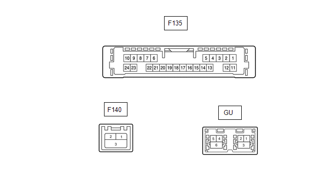
NAVIGATION ECU
|
Terminal No. (Symbol) |
Wiring Color |
Terminal Description |
Condition |
Specified Condition |
|---|---|---|---|---|
|
F135-6 (VOI+) - F135-23 (GND) |
B - W-B*2 W - W-B*3 |
Voice signal |
Voice guidance sounding |
A waveform synchronized with sound is output |
|
F135-7 (VOI-) - F135-23 (GND) |
W - W-B*2 B - W-B*3 |
Voice signal |
Voice guidance sounding |
A waveform synchronized with sound is output |
|
F135-8 (SLD1) - Body ground |
Shielded - Body ground |
Shield ground |
Always |
Below 1 Ω |
|
F135-9 (SPD) - F135-23 (GND) |
V - W-B |
Vehicle speed signal |
See "Check GPS and Vehicle Sensors" in Operation Check
|
- |
|
F135-10 (+B) - F135-23 (GND) |
Y - W-B |
Power source (+B) |
Always |
11 to 14 V |
|
F135-13 (MIC+) - F135-23 (GND) |
W - W-B |
Microphone voice signal |
See "Microphone Check (MEU)" in Operation Check
|
- |
|
F135-14 (MIC-) - Body ground |
B - Body ground |
Microphone voice signal |
See "Microphone Check (MEU)" in Operation Check
|
- |
|
F135-19 (REV2) - F135-23 (GND) |
B - W-B*2 G - W-B*3 |
Reverse signal |
Hybrid control system operating, shift position not in R → in R |
2 V or less → 11 to 14 V |
|
F135-21 (SUP) - F135-23 (GND) |
W - W-B*2 R - W-B*3 |
Power source (ACC) |
20 seconds elapse after turning the engine switch on (ACC) |
11 to 14 V |
|
F135-22 (RST)*1 |
L |
- |
- |
- |
|
F135-23 (GND) - Body ground |
W-B - Body ground |
Ground |
Engine switch off |
Below 1 Ω |
|
F140-1 (USB+) |
- |
USB communication line |
- |
- |
|
F140-2 (USB-) |
- |
USB communication line |
- |
- |
|
F140-3 (USBS) - Body ground |
Shielded - Body ground |
Shield ground |
Always |
Below 1 Ω |
|
GU-1 (GVO-) |
- |
Video signal (Digital) |
- |
- |
|
GU-2 (GVO+) |
- |
Video signal (Digital) |
- |
- |
|
GU-3 (GVG1) - Body ground |
Shielded - Body ground |
Shield ground |
Always |
Below 1 Ω |
|
GU-4 (USB+) |
- |
USB communication line |
- |
- |
|
GU-5 (USB-) |
- |
USB communication line |
- |
- |
|
GU-6 (USBG) - Body ground |
Shielded - Body ground |
Shield ground |
Always |
Below 1 Ω |
- *1: It is connected, but not used
- *2: for TMMT Made
- *3: for TMC Made
DCM (TELEMATICS TRANSCEIVER)
Click here
.gif)
 Problem Symptoms Table
PROBLEM SYMPTOMS TABLE
NOTICE:
Depending on the parts that are replaced during vehicle inspection or
maintenance, performing initialization, registration or calibration may
be needed ...
 Dtc Check / Clear
DTC CHECK / CLEAR
CHECK DTC (CHECK USING TECHSTREAM)
(a) Connect the Techstream to the DLC3.
(b) Turn the engine switch on (IG) and wait for 90 seconds.
(c) Turn the Techstream on.
(d) Enter the ...
Other materials:
Toyota CH-R Owners Manual > Adjusting the steering wheel and mirrors: Outside rear view mirrors
Adjustment procedure
1. To select a mirror to adjust, turn the switch.
Left
Right
2. To adjust the mirror, operate the switch.
Up
Right
Down
Left
Folding and extending the mirrors
Manual type
Push the mirror back in the direction of the rear of the vehicle.
Powe ...
Toyota CH-R Service Manual > Knee Airbag Assembly: On-vehicle Inspection
ON-VEHICLE INSPECTION
CAUTION / NOTICE / HINT
CAUTION:
Be sure to correctly follow the removal and installation procedures for the lower
No. 1 instrument panel airbag assembly.
PROCEDURE
1. INSPECT LOWER NO. 1 INSTRUMENT PANEL AIRBAG ASSEMBLY (for Vehicle not Involved
in Collision)
(a) Per ...
Toyota C-HR (AX20) 2023-2026 Owner's Manual
Toyota CH-R Owners Manual
- For safety and security
- Instrument cluster
- Operation of each component
- Driving
- Interior features
- Maintenance and care
- When trouble arises
- Vehicle specifications
- For owners
Toyota CH-R Service Manual
- Introduction
- Maintenance
- Audio / Video
- Cellular Communication
- Navigation / Multi Info Display
- Park Assist / Monitoring
- Brake (front)
- Brake (rear)
- Brake Control / Dynamic Control Systems
- Brake System (other)
- Parking Brake
- Axle And Differential
- Drive Shaft / Propeller Shaft
- K114 Cvt
- 3zr-fae Battery / Charging
- Networking
- Power Distribution
- Power Assist Systems
- Steering Column
- Steering Gear / Linkage
- Alignment / Handling Diagnosis
- Front Suspension
- Rear Suspension
- Tire / Wheel
- Tire Pressure Monitoring
- Door / Hatch
- Exterior Panels / Trim
- Horn
- Lighting (ext)
- Mirror (ext)
- Window / Glass
- Wiper / Washer
- Door Lock
- Heating / Air Conditioning
- Interior Panels / Trim
- Lighting (int)
- Meter / Gauge / Display
- Mirror (int)
- Power Outlets (int)
- Pre-collision
- Seat
- Seat Belt
- Supplemental Restraint Systems
- Theft Deterrent / Keyless Entry

0.0116