Toyota CH-R Service Manual: Parts Location
PARTS LOCATION
ILLUSTRATION
|
*A |
w/ Navigation System |
- |
- |
|
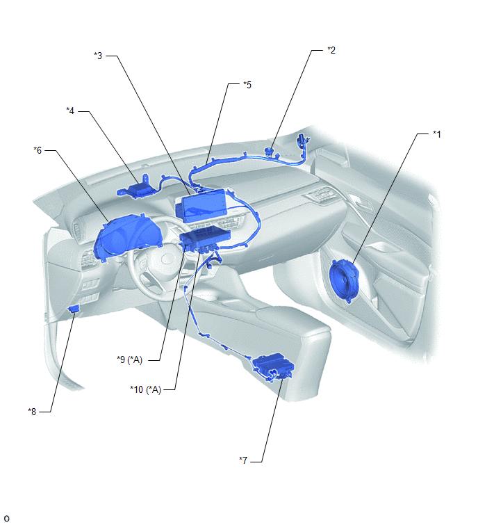
*1 |
FRONT NO. 1 SPEAKER ASSEMBLY RH |
*2 |
FRONT NO. 2 SPEAKER ASSEMBLY RH |
|
*3 |
RADIO AND DISPLAY RECEIVER ASSEMBLY |
*4 |
TELEPHONE AND GPS ANTENNA (FOR FRONT SIDE) - Telephone Sub |
|
*5 |
TELEPHONE AND GPS ANTENNA CORD (ANTENNA CORD SUB-ASSEMBLY) |
*6 |
COMBINATION METER ASSEMBLY |
|
*7 |
DCM (TELEMATICS TRANSCEIVER) |
*8 |
DLC3 |
|
*9 |
NAVIGATION ECU |
*10 |
NO. 1 NAVIGATION WIRE |
ILLUSTRATION
|
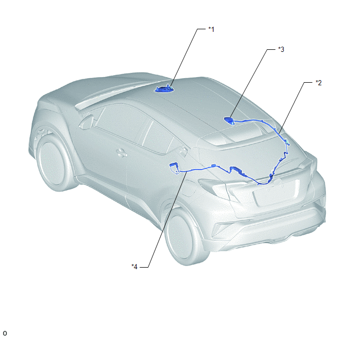
*1 |
MAP LIGHT ASSEMBLY - TELEPHONE MICROPHONE ASSEMBLY |
*2 |
TELEPHONE AND GPS ANTENNA CORD (NO. 3 ANTENNA CORD SUB-ASSEMBLY) |
|
*3 |
TELEPHONE AND GPS ANTENNA (FOR ROOF SIDE) - GPS - Telephone Main |
*4 |
TELEPHONE AND GPS ANTENNA CORD (NO. 6 ANTENNA CORD SUB-ASSEMBLY) |
 Precaution
PRECAUTION
IGNITION SWITCH EXPRESSIONS
(a) The type of ignition switch used on this model differs depending on the specifications
of the vehicle. The expressions listed in the table below are used ...
 System Description
SYSTEM DESCRIPTION
DESCRIPTION
Toyota Entune allows the vehicle to receive information from the call
center and links the information to the audio and visual system. Toyota
Entune per ...
Other materials:
Toyota CH-R Service Manual > Steering Lock System: Dtc Check / Clear
DTC CHECK / CLEAR
NOTICE:
The steering lock ECU (steering lock actuator or upper bracket assembly)
does not store history DTCs. If any DTCs are output, confirm and record
them as soon as possible. Do not turn the engine switch off or clear the
DTCs until the DTCs are confirmed ...
Toyota CH-R Service Manual > Navigation System: Dtc Check / Clear
DTC CHECK / CLEAR
CHECK DTC (CHECK USING TECHSTREAM)
(a) Connect the Techstream to the DLC3.
(b) Turn the engine switch on (IG) and wait for 90 seconds.
(c) Turn the Techstream on.
(d) Enter the following menus: Body Electrical / Navigation System / Trouble
Codes.
Body Electrical > Naviga ...
Toyota C-HR (AX20) 2023-2026 Owner's Manual
Toyota CH-R Owners Manual
- For safety and security
- Instrument cluster
- Operation of each component
- Driving
- Interior features
- Maintenance and care
- When trouble arises
- Vehicle specifications
- For owners
Toyota CH-R Service Manual
- Introduction
- Maintenance
- Audio / Video
- Cellular Communication
- Navigation / Multi Info Display
- Park Assist / Monitoring
- Brake (front)
- Brake (rear)
- Brake Control / Dynamic Control Systems
- Brake System (other)
- Parking Brake
- Axle And Differential
- Drive Shaft / Propeller Shaft
- K114 Cvt
- 3zr-fae Battery / Charging
- Networking
- Power Distribution
- Power Assist Systems
- Steering Column
- Steering Gear / Linkage
- Alignment / Handling Diagnosis
- Front Suspension
- Rear Suspension
- Tire / Wheel
- Tire Pressure Monitoring
- Door / Hatch
- Exterior Panels / Trim
- Horn
- Lighting (ext)
- Mirror (ext)
- Window / Glass
- Wiper / Washer
- Door Lock
- Heating / Air Conditioning
- Interior Panels / Trim
- Lighting (int)
- Meter / Gauge / Display
- Mirror (int)
- Power Outlets (int)
- Pre-collision
- Seat
- Seat Belt
- Supplemental Restraint Systems
- Theft Deterrent / Keyless Entry

0.0079