Toyota CH-R Service Manual: Stereo Jack Adapter Assembly
Components
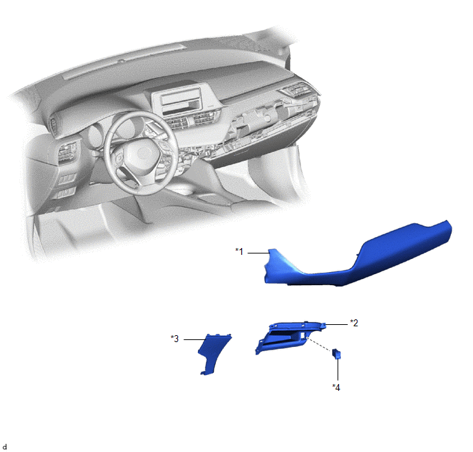
COMPONENTS
ILLUSTRATION
|
*1 |
INSTRUMENT CLUSTER FINISH PANEL GARNISH ASSEMBLY |
*2 |
INSTRUMENT PANEL BOX ASSEMBLY |
|
*3 |
INSTRUMENT PANEL LOWER CENTER FINISH PANEL |
*4 |
NO. 1 STEREO JACK ADAPTER ASSEMBLY |
Installation
INSTALLATION
PROCEDURE
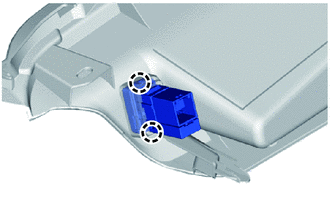
1. INSTALL NO. 1 STEREO JACK ADAPTER ASSEMBLY
|
(a) Engage the claws to install the No. 1 stereo jack adapter assembly. |
|
2. INSTALL INSTRUMENT PANEL BOX ASSEMBLY
Click here
.gif)
3. INSTALL INSTRUMENT PANEL LOWER CENTER FINISH PANEL
Click here
4. INSTALL INSTRUMENT CLUSTER FINISH PANEL GARNISH ASSEMBLY
Click here
Removal
REMOVAL
PROCEDURE
1. REMOVE INSTRUMENT CLUSTER FINISH PANEL GARNISH ASSEMBLY
Click here
.gif)
2. REMOVE INSTRUMENT PANEL LOWER CENTER FINISH PANEL
Click here
3. REMOVE INSTRUMENT PANEL BOX ASSEMBLY
Click here
4. REMOVE NO. 1 STEREO JACK ADAPTER ASSEMBLY
|
(a) Disengage the claws to remove the No. 1 stereo jack adapter assembly. |
|
.png)
 Roof Antenna
Components
COMPONENTS
ILLUSTRATION
*1
ROOF ANTENNA ASSEMBLY
*2
ANTENNA OUTER COVER
*3
HOLDER
*4
SEA ...

Other materials:
Toyota CH-R Service Manual > Rear Seat Outer Belt Assembly: Removal
REMOVAL
CAUTION / NOTICE / HINT
The necessary procedures (adjustment, calibration, initialization, or registration)
that must be performed after parts are removed and installed, or replaced during
the rear seat outer belt assembly removal/installation are shown below.
Necessary Procedure Afte ...
Toyota CH-R Service Manual > Continuously Variable Transaxle System: Torque Converter Clutch Pressure Control Solenoid Control Circuit Electrical
(P2759)
DESCRIPTION
The ECM uses the shift solenoid valve SLU to perform forward and reverse clutch
control or lock-up clutch control.
*1
Spool Valve
*2
Sleeve
*3
Solenoid Coil
-
-
*a
...
Toyota C-HR (AX20) 2023-2026 Owner's Manual
Toyota CH-R Owners Manual
- For safety and security
- Instrument cluster
- Operation of each component
- Driving
- Interior features
- Maintenance and care
- When trouble arises
- Vehicle specifications
- For owners
Toyota CH-R Service Manual
- Introduction
- Maintenance
- Audio / Video
- Cellular Communication
- Navigation / Multi Info Display
- Park Assist / Monitoring
- Brake (front)
- Brake (rear)
- Brake Control / Dynamic Control Systems
- Brake System (other)
- Parking Brake
- Axle And Differential
- Drive Shaft / Propeller Shaft
- K114 Cvt
- 3zr-fae Battery / Charging
- Networking
- Power Distribution
- Power Assist Systems
- Steering Column
- Steering Gear / Linkage
- Alignment / Handling Diagnosis
- Front Suspension
- Rear Suspension
- Tire / Wheel
- Tire Pressure Monitoring
- Door / Hatch
- Exterior Panels / Trim
- Horn
- Lighting (ext)
- Mirror (ext)
- Window / Glass
- Wiper / Washer
- Door Lock
- Heating / Air Conditioning
- Interior Panels / Trim
- Lighting (int)
- Meter / Gauge / Display
- Mirror (int)
- Power Outlets (int)
- Pre-collision
- Seat
- Seat Belt
- Supplemental Restraint Systems
- Theft Deterrent / Keyless Entry

0.0078