Toyota CH-R Owners Manual: Smart key system
The following operations can be performed simply by carrying the electronic key on your person, for example in your pocket.
The driver should always carry the electronic key.
- Unlocks and locks the doors
- Unlocks and locks the back door
- Starts the engine
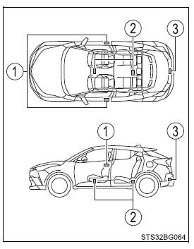
■Antenna location
- Antenna outside the cabin
- Antennas inside the cabin
- Antenna outside the luggage compartment

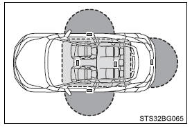
■Effective range (areas within which the electronic key is detected)
 When
locking or unlocking the doors
The system can be operated when the electronic key is within about 2.3 ft. (0.7 m) of an outside front door handle and the back door.
(Only the doors detecting the key can be operated.)
 When
starting the engine or changing engine switch modes
The system can be operated when the electronic key is inside the vehicle.

■Alarms and warning messages A combination of exterior and interior buzzers as well as warning messages shown on the multi-information display are used to prevent theft of the vehicle and accidents resulting from erroneous operation. Take appropriate measures based on the displayed message. When only an alarm sounds, circumstances and correction procedures are as follows.
| Alarm | Situation | Correction procedure |
| Exterior buzzer sounds once for 5 seconds | An attempt was made to lock the vehicle while a door was open. | Close all of the doors and lock the doors again. |
| Interior buzzer sounds continuously | The engine switch was turned to ACCESSORY mode while the driver's door was open (or the driver's door was opened while the engine switch was in ACCESSORY mode). | Turn the engine switch off and close the driver's door. |
■When "Smart Key System malfunction. See owner's manual" is displayed on the multi-information display The system may be malfunctioning. Have the vehicle inspected by your Toyota dealer immediately.
■Battery-saving function The battery-saving function will be activated in order to prevent the electronic key battery and the vehicle battery from being discharged while the vehicle is not in operation for a long time.
- In the following situations, the smart key system may take some time to
unlock the doors.
- The electronic key has been left in an area of approximately 6 ft. (2 m) of the outside of the vehicle for 10 minutes or longer.
- The smart key system has not been used for 5 days or longer.
- If the smart key system has not been used for 14 days or longer, the doors cannot be unlocked at any doors except the driver's door. In this case, take hold of the driver's door handle, or use the wireless remote control or the mechanical key, to unlock the doors.
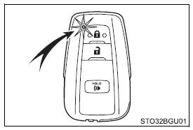
■Electronic key battery-saving function When battery-saving mode is set, battery depletion is minimized by stopping the electronic key from receiving radio waves.
Press
 twice
while pressing and holding
 . Confirm that the electronic key indicator flashes 4 times.
While the battery-saving mode is set, the smart key system cannot be used. To cancel the function, press any of the electronic key buttons.

■Conditions affecting operation The smart key system uses weak radio waves. In the following situations, the communication between the electronic key and the vehicle may be affected, preventing the smart key system, wireless remote control and engine immobilizer system from operating properly.
- When the electronic key battery is depleted
- Near a TV tower, electric power plant, gas station, radio station, large display, airport or other facility that generates strong radio waves or electrical noise
- When carrying a portable radio, cellular phone, cordless phone or other wireless communication device
- When the electronic key is in contact with, or is covered by the following
metallic objects
- Cards to which aluminum foil is attached
- Cigarette boxes that have aluminum foil inside
- Metallic wallets or bags
- Coins
- Hand warmers made of metal
- Media such as CDs and DVDs
- When other wireless keys (that emit radio waves) are being used nearby
- When carrying the electronic key together with the following devices that
emit radio waves
- Portable radio, cellular phone, cordless phone or other wireless communication devices
- Another electronic key or a wireless key that emits radio waves
- Personal computers or personal digital assistants (PDAs)
- Digital audio players
- Portable game systems
- If window tint with a metallic content or metallic objects are attached to the rear window
- When the electronic key is placed near a battery charger or electronic devices
- When parking at a meter
■Note for the entry function
- Even when the electronic key is within the effective range (detection areas),
the system may not operate properly in the following cases:
- The electronic key is too close to the window or outside door handle, near the ground, or in a high place when the doors are locked or unlocked.
- The electronic key is near the ground or in a high place, or too close to the rear bumper center when the back door is opened.
- The electronic key is on the instrument panel, luggage cover or floor, or in the door pockets or glove box when the engine is started or engine switch modes are changed.
- Do not leave the electronic key on top of the instrument panel or near the door pockets when exiting the vehicle. Depending on the radio wave reception conditions, it may be detected by the antenna outside the cabin and the door will become lockable from the outside, possibly trapping the electronic key inside the vehicle.
- As long as the electronic key is within the effective range, the doors may be unlocked or locked by anyone.
- Even if the electronic key is not inside the vehicle, it may be possible to start the engine if the electronic key is near the window.
- The doors may unlock if a large amount of water splashes on the door handle, such as in the rain or in a car wash when the electronic key is within the effective range. (The door will automatically be locked after approximately 60 seconds if the doors are not opened and closed.)
- If the wireless remote control is used to lock the doors when the electronic key is near the vehicle, there is a possibility that the door may not be unlocked by the entry function. (Use the wireless remote control to unlock the doors.)
- Touching the door lock sensor while wearing gloves may delay or prevent lock operation. Remove the gloves and touch the lock sensor again.
- If the door handle becomes wet while the electronic key is within the effective
range, the door may lock and unlock repeatedly. In this case, follow the following
correction procedures to wash the vehicle.
- Place the electronic key in a location 6 ft. (2 m) or more away from the vehicle. (Take care to ensure that the key is not stolen.)
- Set electronic key to battery-saving mode to disable the smart key system.
- If the electronic key is inside the vehicle and a door handle becomes wet during a car wash, a message may be shown on the multi-information display and a buzzer will sound outside the vehicle. To turn off the alarm, lock all the doors.
- The lock sensor may not work properly if it comes into contact with ice, snow, mud, etc. Clean the lock sensor and attempt to operate it again.
- A sudden approach to the effective range or door handle may prevent the doors from being unlocked. In this case, return the door handle to the original position and check that the doors unlock before pulling the door handle again.
- If there is another electronic key in the detection area, it may take slightly longer to unlock the doors after the door handle is gripped.
- Fingernails may scrape against the door during operation of the door handle.
Be careful not to injure fingernails or damage the surface of the door.
■When the vehicle is not driven for extended periods
- To prevent theft of the vehicle, do not leave the electronic key within 6 ft. (2 m) of the vehicle.
- The smart key system can be deactivated in advance.
■To operate the system properly Make sure to carry the electronic key when operating the system. Do not get the electronic key too close to the vehicle when operating the system from the outside of the vehicle.
Depending on the position and holding condition of the electronic key, the key may not be detected correctly and the system may not operate properly. (The alarm may go off accidentally, or the door lock prevention may not operate.)
■If the smart key system does not operate properly
- Locking and unlocking the doors: Use the mechanical key.
- Starting the engine system
■Customization Settings (e.g. smart key system) can be changed.
■If the smart key system has been deactivated in a customized setting
- Unlocking and locking the doors:
Use the wireless remote control or mechanical key. - Starting the engine and changing engine switch modes
- Stopping the engine
■Caution regarding interference with electronic devices
- People with implantable cardiac pacemakers, cardiac resynchronization
therapy-pacemakers or implantable cardioverter defibrillators should keep
away from the smart key system antennas. The radio waves may affect the
operation of such devices. If necessary, the entry function can be disabled.
Ask your Toyota dealer for details, such as the frequency of radio waves
and timing of the emitted radio waves.
Then, consult your doctor to see if you should disable the entry function.
- Users of any electrical medical device other than implantable cardiac
pacemakers, cardiac resynchronization therapy-pacemakers or implantable
cardioverter defibrillators should consult the manufacturer of the device
for information about its operation under the influence of radio waves.
Radio waves could have unexpected effects on the operation of such medical devices.
Ask your Toyota dealer for details on disabling the entry function.
 Back door
The back door can be locked/unlocked and opened by the following
procedures.
Unlocking and locking the back door
Entry function (vehicles with a smart key system)
Press the button to unlock th ...
Other materials:
Toyota CH-R Service Manual > Safety Connect System: Backup Battery Failure (B15CC)
DESCRIPTION
This DTC is set when the DCM (Telematics Transceiver) detects one of the following:
The BUB (Back-Up Battery) voltage drops or the BUB (Back-Up Battery)
malfunctions.
The BUB (Back-Up Battery) temperature is (temporarily) high.
DTC No.
Detect ...
Toyota CH-R Service Manual > Air Conditioning System(for Automatic Air Conditioning System With Top-mounted
Air Conditioner Pressure Sensor): Ambient Temperature Sensor Circuit (B1412)
DESCRIPTION
The thermistor assembly is installed in front of the cooler condenser assembly
to detect the ambient temperature, which is used to control the air conditioning
system. This sensor is connected to the combination meter assembly and detects fluctuations
in the ambient temperature. T ...
Toyota C-HR (AX20) 2023-2026 Owner's Manual
Toyota CH-R Owners Manual
- For safety and security
- Instrument cluster
- Operation of each component
- Driving
- Interior features
- Maintenance and care
- When trouble arises
- Vehicle specifications
- For owners
Toyota CH-R Service Manual
- Introduction
- Maintenance
- Audio / Video
- Cellular Communication
- Navigation / Multi Info Display
- Park Assist / Monitoring
- Brake (front)
- Brake (rear)
- Brake Control / Dynamic Control Systems
- Brake System (other)
- Parking Brake
- Axle And Differential
- Drive Shaft / Propeller Shaft
- K114 Cvt
- 3zr-fae Battery / Charging
- Networking
- Power Distribution
- Power Assist Systems
- Steering Column
- Steering Gear / Linkage
- Alignment / Handling Diagnosis
- Front Suspension
- Rear Suspension
- Tire / Wheel
- Tire Pressure Monitoring
- Door / Hatch
- Exterior Panels / Trim
- Horn
- Lighting (ext)
- Mirror (ext)
- Window / Glass
- Wiper / Washer
- Door Lock
- Heating / Air Conditioning
- Interior Panels / Trim
- Lighting (int)
- Meter / Gauge / Display
- Mirror (int)
- Power Outlets (int)
- Pre-collision
- Seat
- Seat Belt
- Supplemental Restraint Systems
- Theft Deterrent / Keyless Entry
0.0103

