Toyota CH-R Service Manual: Radio Broadcast cannot be Received or Poor Reception
WIRING DIAGRAM
for TMMT Made
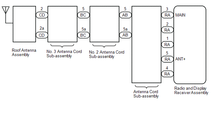
for TMC Made

CAUTION / NOTICE / HINT
NOTICE:
- Depending on the parts that are replaced during vehicle inspection or
maintenance, performing initialization, registration or calibration may
be needed. Refer to Precaution for Audio and Visual System.
Click here
.gif)
- When replacing the radio and display receiver assembly, always replace
it with a new one. If a radio and display receiver assembly which was installed
to another vehicle is used, the following may occurs:
- A communication malfunction DTC may be stored.
- The radio and display receiver assembly may not operate normally.
PROCEDURE
|
1. |
CHECK RADIO AND DISPLAY RECEIVER ASSEMBLY |
(a) Check the radio automatic station search function.
(1) Check the radio automatic station search function by activating it.
|
Result |
Proceed to |
|---|---|
|
Automatic station search function does not stop |
A |
|
Automatic station search function stops on a station |
B |
| B | .gif) |
REPLACE RADIO AND DISPLAY RECEIVER ASSEMBLY |
|
.gif)
|
2. |
CHECK OPTIONAL COMPONENTS |
(a) Check if any optional components that may decrease reception capacity, such as sunshade film or a telephone antenna, are installed.
|
Result |
Proceed to |
|---|---|
|
Optional components are not installed |
A |
|
Optional components are installed |
B |
NOTICE:
Do not remove optional components without the permission of the customer.
| B | |
REMOVE OPTIONAL COMPONENTS AND CHECK AGAIN (SEE NOTICE ABOVE) |
|
|
3. |
CHECK RADIO AND DISPLAY RECEIVER ASSEMBLY |
|
(a) Preparation for check (1) Disconnect the antenna connector from the radio and display receiver assembly. |
|
(b) Check for noise
(1) Turn the ignition switch to ACC with the radio and display receiver assembly connector connected.
(2) Turn the radio on and tune into AM mode.
(3) Place a screwdriver, thin wire or other metal object on the radio and display receiver assembly antenna jack and check that noise can be heard from the speakers.
OK:
Noise can be heard from the speakers.
| NG | |
REPLACE RADIO AND DISPLAY RECEIVER ASSEMBLY |
|
|
4. |
INSPECT RADIO AND DISPLAY RECEIVER ASSEMBLY |
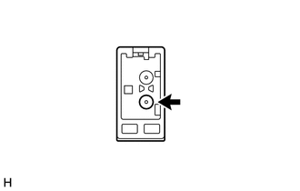
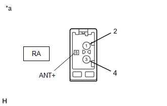
(a) Disconnect the RA radio and display receiver assembly connector.
|
(b) Measure the voltage according to the value(s) in the table below. Standard Voltage:
|
|
| NG | |
REPLACE RADIO AND DISPLAY RECEIVER ASSEMBLY |
|
|
5. |
REPLACE ANTENNA CORD SUB-ASSEMBLY |
(a) Replace the antenna cord sub-assembly with a new or known good one and check if radio broadcasts can be received normally.
Click here
OK:
Radio broadcasts can be received normally.
|
Result |
Proceed to |
|---|---|
|
OK |
A |
|
NG (for TMMT Made) |
B |
|
NG (for TMC Made) |
C |
| A | |
END (ANTENNA CORD SUB-ASSEMBLY WAS DEFECTIVE) |
| C | |
GO TO STEP 9 |
|
|
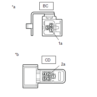
6. |
CHECK NO. 2 ANTENNA CORD SUB-ASSEMBLY |
|
(a) Disconnect the No. 2 antenna cord sub-assembly connector from the antenna cord sub-assembly. |
|
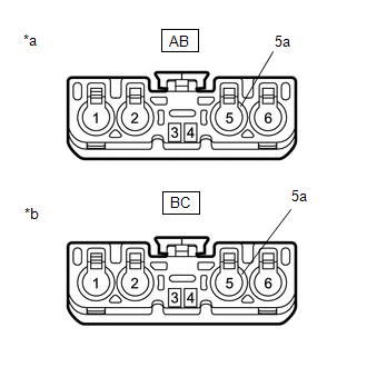
(b) Disconnect the No. 2 antenna cord sub-assembly connector from the No. 3 antenna Cord sub-assembly.
(c) Measure the resistance according to the value(s) in the table below.
Standard Resistance:
|
Tester Connection |
Condition |
Specified Condition |
|---|---|---|
|
AB-5 - BC-5 |
Always |
Below 1 Ω |
|
AB-5a - BC-5a |
Always |
Below 1 Ω |
|
AB-5 - Body ground |
Always |
10 kΩ or higher |
|
AB-5a - Body ground |
Always |
10 kΩ or higher |
| NG | |
REPLACE NO. 2 ANTENNA CORD SUB-ASSEMBLY |
|
|
7. |
CHECK NO. 3 ANTENNA CORD SUB-ASSEMBLY |
|
(a) Disconnect the No. 3 antenna cord sub-assembly connector from the No. 2 antenna cord sub-assembly. |
|
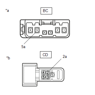
(b) Disconnect the No. 3 antenna cord sub-assembly connector from the roof antenna assembly.
(c) Measure the resistance according to the value(s) in the table below.
Standard Resistance:
|
Tester Connection |
Condition |
Specified Condition |
|---|---|---|
|
BC-5 - CD2 |
Always |
Below 1 Ω |
|
BC-5a - CD-2a |
Always |
Below 1 Ω |
|
BC-5 - Body ground |
Always |
10 kΩ or higher |
|
BC-5a - Body ground |
Always |
10 kΩ or higher |
| NG | |
REPLACE NO. 3 ANTENNA CORD SUB-ASSEMBLY |
|
|
8. |
REPLACE ROOF ANTENNA ASSEMBLY |
(a) Replace the roof antenna assembly with a new or known good one and check if radio broadcasts can be received normally.
Click here
OK:
Radio broadcasts can be received normally.
| OK | |
END (ROOF ANTENNA ASSEMBLY WAS DEFECTIVE) |
| NG | |
REPLACE RADIO AND DISPLAY RECEIVER ASSEMBLY |
|
9. |
CHECK NO. 2 ANTENNA CORD SUB-ASSEMBLY |
|
(a) Disconnect the No. 2 antenna cord sub-assembly connector from the antenna cord sub-assembly. |
|
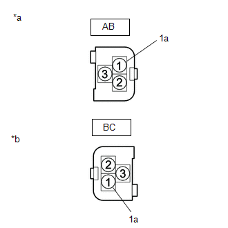
(b) Disconnect the No. 2 antenna cord sub-assembly connector from the No. 3 antenna Cord sub-assembly.
(c) Measure the resistance according to the value(s) in the table below.
Standard Resistance:
|
Tester Connection |
Condition |
Specified Condition |
|---|---|---|
|
AB-1 - BC-1 |
Always |
Below 1 Ω |
|
AB-1a - BC-1a |
Always |
Below 1 Ω |
|
AB-1 - Body ground |
Always |
10 kΩ or higher |
|
AB-1a - Body ground |
Always |
10 kΩ or higher |
| NG | |
REPLACE NO. 2 ANTENNA CORD SUB-ASSEMBLY |
|
|
10. |
CHECK NO. 3 ANTENNA CORD SUB-ASSEMBLY |
|
(a) Disconnect the No. 3 antenna cord sub-assembly connector from the antenna cord sub-assembly. |
|
(b) Disconnect the No. 3 antenna cord sub-assembly connector from the telephone antenna assembly.
(c) Measure the resistance according to the value(s) in the table below.
Standard Resistance:
|
Tester Connection |
Condition |
Specified Condition |
|---|---|---|
|
BC-1 - CD-2 |
Always |
Below 1 Ω |
|
BC-1a - CD-2a |
Always |
Below 1 Ω |
|
BC-1 - Body ground |
Always |
10 kΩ or higher |
|
BC-1a - Body ground |
Always |
10 kΩ or higher |
| NG | |
REPLACE NO. 3 ANTENNA CORD SUB-ASSEMBLY |
|
|
11. |
REPLACE ROOF ANTENNA ASSEMBLY |
(a) Replace the roof antenna assembly with a new or known good one and check if radio broadcasts can be received normally.
Click here
OK:
Radio broadcasts can be received normally.
| OK | |
END (ROOF ANTENNA ASSEMBLY WAS DEFECTIVE) |
| NG | |
REPLACE RADIO AND DISPLAY RECEIVER ASSEMBLY |
 Noise Occurs
PROCEDURE
1.
CHECK NOISE CONDITION
(a) Check from which direction the noise comes (front left or right, or rear
left or right).
OK:
The location of the noise sou ...
 Illumination for Panel Switch does not Come on with Tail Switch ON
CAUTION / NOTICE / HINT
NOTICE:
Depending on the parts that are replaced during vehicle inspection or
maintenance, performing initialization, registration or calibration may
be neede ...
Other materials:
Toyota CH-R Service Manual > Toyota Entune System: Lost Communication with Body Control Module "B" (U0142,U0155,U0163)
DESCRIPTION
These DTCs are stored when a malfunction occurs in the CAN communication circuit.
HINT:
If CAN communication system DTCs are stored, they may also be stored for other
systems.
DTC No.
Detection Item
DTC Detection Condition
Trouble Area
...
Toyota CH-R Service Manual > Generator: Reassembly
REASSEMBLY
PROCEDURE
1. INSTALL GENERATOR DRIVE END FRAME BEARING
(a) Using SST and a press, install a new generator drive end frame bearing.
SST: 09950-60010
09951-00470
SST: 09950-70010
09951-07100
(b) Fit the ta ...
Toyota C-HR (AX20) 2023-2026 Owner's Manual
Toyota CH-R Owners Manual
- For safety and security
- Instrument cluster
- Operation of each component
- Driving
- Interior features
- Maintenance and care
- When trouble arises
- Vehicle specifications
- For owners
Toyota CH-R Service Manual
- Introduction
- Maintenance
- Audio / Video
- Cellular Communication
- Navigation / Multi Info Display
- Park Assist / Monitoring
- Brake (front)
- Brake (rear)
- Brake Control / Dynamic Control Systems
- Brake System (other)
- Parking Brake
- Axle And Differential
- Drive Shaft / Propeller Shaft
- K114 Cvt
- 3zr-fae Battery / Charging
- Networking
- Power Distribution
- Power Assist Systems
- Steering Column
- Steering Gear / Linkage
- Alignment / Handling Diagnosis
- Front Suspension
- Rear Suspension
- Tire / Wheel
- Tire Pressure Monitoring
- Door / Hatch
- Exterior Panels / Trim
- Horn
- Lighting (ext)
- Mirror (ext)
- Window / Glass
- Wiper / Washer
- Door Lock
- Heating / Air Conditioning
- Interior Panels / Trim
- Lighting (int)
- Meter / Gauge / Display
- Mirror (int)
- Power Outlets (int)
- Pre-collision
- Seat
- Seat Belt
- Supplemental Restraint Systems
- Theft Deterrent / Keyless Entry

0.0095