Toyota CH-R Service Manual: Terminals Of Ecu
TERMINALS OF ECU
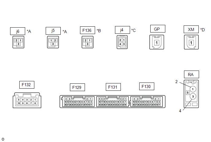
RADIO AND DISPLAY RECEIVER ASSEMBLY
|
*A |
w/ Navigation System |
*B |
w/ Manual (SOS) Switch |
|
*C |
w/o Navigation System |
*D |
for Satellite Radio |
|
Terminal No. (Symbol) |
Wiring Color |
Terminal Description |
Condition |
Specified Condition |
|---|---|---|---|---|
|
F129-1 (GND1) - Body ground |
LA - Body ground |
Ground |
Always |
Below 1 V |
|
F129-4 (+B1) - F129-1 (GND1) |
LA-SB - LA |
Power source (+B) |
Always |
11 to 14 V |
|
F129-11 (VAL+) - F129-13 (VA-) |
B - R |
Sound signal (Left) |
External device playing (When stereo jack used) |
A waveform synchronized with sounds is output |
|
F129-12 (VAR+) - F129-13 (VA-) |
W - R |
Sound signal (Right) |
External device playing (When stereo jack used) |
A waveform synchronized with sounds is output |
|
F129-13 (VA-) - Body ground |
R - Body ground |
Ground |
Always |
Below 1 V |
|
F129-14 (ADPG) - F129-1 (GND1) |
R - LA |
External device connection detection signal |
External device connected |
Below 1 V |
|
External device not connected |
2.1 to 3 V |
|||
|
F129-15 (ACC1) - F129-1 (GND1) |
GR - LA |
Power source (ACC) |
Ignition switch off |
Below 1 V |
|
Ignition switch ACC |
11 to 14 V |
|||
|
F129-21 (SW1) - F129-24 (SWG) |
GR - W-B |
Steering pad switch signal |
No switch pushed |
2.97 to 3.56 V |
|
Seek+ switch pushed |
0.27 to 0.35 V |
|||
|
Seek- switch pushed |
0.86 to 1.03 V |
|||
|
Volume+ switch pushed |
1.51 to 1.79 V |
|||
|
Volume- switch pushed |
2.22 to 2.66 V |
|||
|
F129-22 (SW2) - F129-24 (SWG) |
G - W-B |
Steering pad switch signal |
No switch pushed |
2.97 to 3.56 V |
|
MODE switch pushed |
0.27 to 0.35 V |
|||
|
Off hook switch pushed |
1.51 to 1.79 V |
|||
|
On hook switch pushed |
0.86 to 1.03 V |
|||
|
Voice switch pushed |
2.22 to 2.66 V |
|||
|
F129-27 (SPD) - F129-1 (GND1) |
V - LA |
Vehicle speed signal |
See "Check Vehicle Signal" in Operation Check
|
- |
|
F129-28 (REV) - F129-1 (GND1) |
R - LA*1 L - LA*2 |
Reverse signal |
See "Check Vehicle Signal" in Operation Check
|
- |
|
F129-10 (AGND) - Body ground |
Shield - Body ground |
Shield ground |
Always |
Below 1 V |
|
F130-13 (VOR+) - F129-1 (GND1)*3 |
G - LA |
Receive voice signal |
Receiving a call while using the operator service |
A waveform synchronized with the received voice is output |
|
F130-14 (VOR-) - F129-1 (GND1)*3 |
W - LA |
Receive voice signal |
Receiving a call while using the operator service |
A waveform synchronized with the received voice is output |
|
F130-15 (VOT+) - F129-1 (GND1)*3 |
R - LA |
Sent voice signal |
Calling while using the operator service |
A waveform synchronized with the sent voice is output |
|
F130-16 (VOT-) - F129-1 (GND1)*3 |
B - LA |
Sent voice signal |
Calling while using the operator service |
A waveform synchronized with the sent voice is output |
|
F131-3 (TMUT) - F129-1 (GND1)*3 |
L - LA |
Mute signal |
Ignition switch ACC Audio system playing |
2.0 V or higher |
|
Emergency call mode |
Below 1 V |
|||
|
F131- 5 (CNH1) |
R |
Local bus communication signal |
- |
- |
|
F131-6 (CNL1) |
L |
Local bus communication signal |
- |
- |
|
F131-13 (CANH) |
B |
CAN communication signal |
- |
- |
|
F131-14 (CANL) |
LG |
CAN communication signal |
- |
- |
|
F131-19 (IG) - F129-1 (GND1) |
B - LA |
Power source (IG) |
Ignition switch off |
Below 1 V |
|
Ignition switch ON |
11 to 14 V |
|||
|
F131-20 (PKB) - F129-1 (GND1) |
P - LA |
Parking brake signal |
See "Check Vehicle Signal" in Operation Check
|
- |
|
F131-21 (MIN+) - F129-1 (GND1) |
W - LA |
Microphone voice signal |
See "Check Vehicle Signal" in Operation Check
|
- |
|
F131-22 (MIN-) - F129-1 (GND1) |
R - LA |
Microphone voice signal |
See "Check Vehicle Signal" in Operation Check
|
- |
|
F131-23 (MACC) - F129-1 (GND1) |
B - LA |
Microphone power supply |
Ignition switch off |
Below 1 V |
|
Ignition switch ON |
4 to 6 V |
|||
|
F131-24 (SGND) - Body ground |
Shield - Body ground |
Shield ground |
Always |
Below 1 Ω |
|
F131-25 (SNS2) - F129-1 (GND1) |
V - LA*1 G - LA*2 |
Microphone connection detection signal |
Always |
Below 1 V |
|
F132-1 (FR+) - F129-1 (GND1) |
LA-L - LA*3 P - LA*4 |
Sound signal (Front right) |
Audio system playing |
A waveform synchronized with sound is output |
|
F132-2 (FL+) - F129-1 (GND1) |
W - LA |
Sound signal (Front left) |
Audio system playing |
A waveform synchronized with sound is output |
|
F132-3 (RL+) - F129-1 (GND1) |
B - LA |
Sound signal (Rear left) |
Audio system playing |
A waveform synchronized with sound is output |
|
F132-4 (RR+) - F129-1 (GND1) |
R - LA |
Sound signal (Rear right) |
Audio system playing |
A waveform synchronized with sound is output |
|
F132-6 (FR-) - F129-1 (GND1) |
LA-L - LA*3 BR - LA*4 |
Sound signal (Front right) |
Audio system playing |
A waveform synchronized with sound is output |
|
F132-7 (FL-) - F129-1 (GND1) |
B - LA |
Sound signal (Front left) |
Audio system playing |
A waveform synchronized with sound is output |
|
F132-8 (RL-) - F129-1 (GND1) |
Y - LA |
Sound signal (Rear left) |
Audio system playing |
A waveform synchronized with sound is output |
|
F132-9 (RR-) - F129-1 (GND1) |
W - LA |
Sound signal (Rear right) |
Audio system playing |
A waveform synchronized with sound is output |
|
F136-1 (USB+) |
- |
USB communication line |
- |
- |
|
F136-2 (USB-) |
- |
USB communication line |
- |
- |
|
F136-3 (USBS) - Body ground |
Shield - Body ground |
Shield ground |
Always |
Below 1 Ω |
|
j4-1 (USV1) |
- |
Power source |
- |
- |
|
j4-2 (US1-) |
- |
Data signal |
- |
- |
|
j4-3 (US1+) |
- |
Data signal |
- |
- |
|
j4-4 (UGD1) |
- |
Ground |
- |
- |
|
j5-1 (USB+) |
- |
Data signal |
- |
- |
|
j5-2 (USB-) |
- |
Data signal |
- |
- |
|
j5-3 (USBG) |
- |
Ground |
- |
- |
|
j6-1 (GV-) |
- |
Video signal (Digital) |
- |
- |
|
j6-2 (GV+) |
- |
Video signal (Digital) |
- |
- |
|
j6-3 (GND) |
Shield - Body ground |
Shield ground |
Always |
Below 1 Ω |
- *1: for TMMT made
*2: for TMC made
*3: w/ Manual (SOS) Switch
*4: w/o Manual (SOS) Switch
DCM (TELEMATICS TRANSCEIVER) (w/ Manual (SOS) Switch)
Click here
.gif)
 Problem Symptoms Table
PROBLEM SYMPTOMS TABLE
NOTICE:
When replacing the radio and display receiver assembly or navigation
ECU, always replace it with a new one. If a radio and display receiver assembly
or ...
 Dtc Check / Clear
DTC CHECK / CLEAR
CHECK DTC (CHECK USING Techstream)
(a) Connect the Techstream to the DLC3.
(b) Turn the ignition switch to ON.
(c) Turn the Techstream on.
(d) Enter the following menus: Body El ...
Other materials:
Toyota CH-R Service Manual > Seat Belt Warning System(w/ Occupant Classification System): On-vehicle Inspection
ON-VEHICLE INSPECTION
PROCEDURE
1. INSPECT DRIVER SEAT BELT WARNING LIGHT
HINT:
The seat belt warning light on the combination meter assembly is used for both
the driver seat and front passenger seat.
(a) Turn the ignition switch to ON.
(b) When the driver seat belt is not fastened, check th ...
Toyota CH-R Service Manual > Seat Heater System: Diagnosis System
DIAGNOSIS SYSTEM
DESCRIPTION
(a) Seat heater system data and Diagnostic Trouble Codes (DTCs) can be read through
the Data Link Connector 3 (DLC3) of the vehicle. When the system seems to be malfunctioning,
use the Techstream to check for malfunctions and perform troubleshooting.
CHECK DLC3
( ...
Toyota C-HR (AX20) 2023-2026 Owner's Manual
Toyota CH-R Owners Manual
- For safety and security
- Instrument cluster
- Operation of each component
- Driving
- Interior features
- Maintenance and care
- When trouble arises
- Vehicle specifications
- For owners
Toyota CH-R Service Manual
- Introduction
- Maintenance
- Audio / Video
- Cellular Communication
- Navigation / Multi Info Display
- Park Assist / Monitoring
- Brake (front)
- Brake (rear)
- Brake Control / Dynamic Control Systems
- Brake System (other)
- Parking Brake
- Axle And Differential
- Drive Shaft / Propeller Shaft
- K114 Cvt
- 3zr-fae Battery / Charging
- Networking
- Power Distribution
- Power Assist Systems
- Steering Column
- Steering Gear / Linkage
- Alignment / Handling Diagnosis
- Front Suspension
- Rear Suspension
- Tire / Wheel
- Tire Pressure Monitoring
- Door / Hatch
- Exterior Panels / Trim
- Horn
- Lighting (ext)
- Mirror (ext)
- Window / Glass
- Wiper / Washer
- Door Lock
- Heating / Air Conditioning
- Interior Panels / Trim
- Lighting (int)
- Meter / Gauge / Display
- Mirror (int)
- Power Outlets (int)
- Pre-collision
- Seat
- Seat Belt
- Supplemental Restraint Systems
- Theft Deterrent / Keyless Entry

0.009