Toyota CH-R Service Manual: Operation Check
OPERATION CHECK
STORAGE CHECK (DCU STORAGE CHECK)
NOTICE:
When replacing the radio and display receiver assembly, always replace it with a new one. If a radio and display receiver assembly which was installed to another vehicle is used, the following may occur:
- A communication malfunction DTC is stored.
- The radio and display receiver assembly may not operate normally.
HINT:
- Check the storage with it installed to the radio and display receiver assembly.
- Illustrations may differ from the actual vehicle screen depending on the device settings and options. Therefore, some detailed areas may not be shown exactly the same as on the actual vehicle screen.
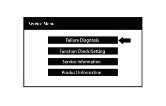
(a) Enter diagnostic mode.
Click here
.gif)
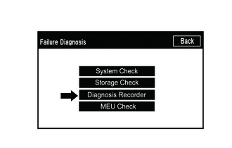
(b) Select "Failure Diagnosis" from the "Service Menu" screen.
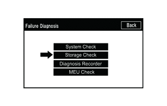
(c) Select "Storage Check" from the "Failure Diagnosis" screen.
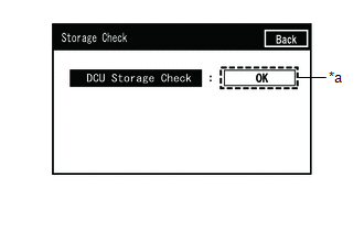
(d) Storage Check
|
*a |
Result |
(1) Select "DCU Storage Check" to start the DCU storage check.
(2) Check the result displayed when the DCU storage check is complete.
Screen Description|
Display (Result) |
Description |
|---|---|
|
Checking |
Check is in progress |
|
OK |
Radio and display receiver assembly storage is normal |
|
NG |
Radio and display receiver assembly storage is malfunctioning |
HINT:
- After selecting "DCU Storage Check", it may take a while until the result is displayed.
- If the cabin temperature is -20°C (-4°F) or lower, or 65°C (149°F) or higher, the storage may not operate normally, and "NG" may be shown on the display. Make sure to perform troubleshooting with the cabin at an appropriate temperature.
- If "NG" is displayed even when the cabin temperature is appropriate, replace the radio and display receiver assembly with a new one.
CHECK PANEL & STEERING SWITCH
HINT:
- The radio and display receiver assembly panel switches and steering switches are checked in the following procedure.
- Illustrations may differ from the actual vehicle screen depending on the device settings and options. Therefore, some detailed areas may not be shown exactly the same as on the actual vehicle screen.
(a) Enter diagnostic mode.
Click here
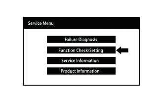
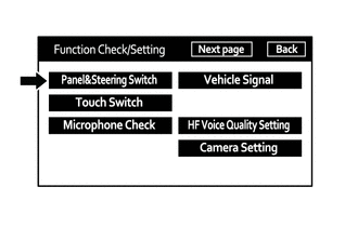
(b) Select "Function Check/Setting" from the "Service Menu" screen.
(c) Select "Panel & Steering Switch" from the "Function Check/Setting I" screen.
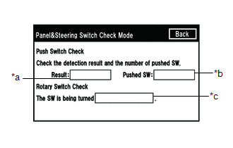
(d) Panel & Steering Switch Check Mode
 Screen Description
|
Display |
Content |
|---|---|
|
*a: Switch condition |
"Pushed" is displayed when any switch is pushed. |
|
*b: Number of switches pushed |
|
|
*c: Rotary switch direction |
Direction of rotary switch is displayed. |
(1) Operate each switch and check that the switch conditions are correctly displayed.
NOTICE:
When the "SETUP" switch is pressed and held for 3 seconds or more, diagnostic mode will be canceled.
CHECK TOUCH SWITCH
HINT:
- The touch switches on the screen are checked in the following procedure.
- Illustrations may differ from the actual vehicle screen depending on the device settings and options. Therefore, some detailed areas may not be shown exactly the same as on the actual vehicle screen.
(a) Enter diagnostic mode.
Click here
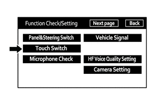
(b) Select "Function Check/Setting" from the "Service Menu" screen.
(c) Select "Touch Switch" from the "Function Check/Setting I" screen.
(d) Touch Switch Check
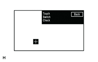
(1) Touch the display anywhere in the open area to perform the check when the "Touch Switch Check" screen is displayed.
HINT:
- A "+" mark is displayed where the display is touched.
- The "+" mark remains on the display even after your finger is removed.
CHECK MICROPHONE (INPUT TO RADIO AND DISPLAY RECEIVER ASSEMBLY)
HINT:
- The radio and display receiver assembly microphone and microphone input signal can be checked using the following procedures.
- Illustrations may differ from the actual vehicle screen depending on the device settings and options. Therefore, some detailed areas may not be shown exactly the same as on the actual vehicle screen.
(a) Enter diagnostic mode.
Click here
(b) Select "Function Check/Setting" from the "Service Menu" screen.
(c) Select "Microphone Check" from the "Function Check/Setting I" screen.
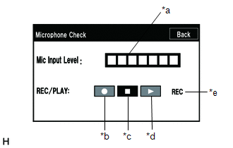
(d) Microphone Check
 Screen Description
|
Display |
Content |
|---|---|
|
*a: Microphone input level meter |
Monitors the microphone input level every 0.1 seconds and displays the results in 8 different levels. |
|
*b: Recording switch |
Starts recording. |
|
*c: Stop switch |
Stops recording and playing. |
|
*d: Play switch |
Plays the recorded voice. |
|
*e: Recording indicator |
Comes on while recording. |
(1) When speaking into the microphone, check that the microphone input level meter changes according to the input level.
HINT:
The microphone is active at all times when this screen is displayed.
(2) Push the recording switch and perform voice recording.
HINT:
- Select the recording switch with the blower motor of the air conditioning system stopped. If an outlet of the air conditioning system is facing the microphone, noise may be recorded.
- While recording or playing, the switches other than the stop switch cannot be pushed.
- When no recording is present, the play switch cannot be pushed.
- Recording will stop after 5 seconds or when the stop switch is pushed.
(3) Check that the recording indicator remains on while recording and that the recording can be played normally.
CHECK GPS & VEHICLE SENSORS
HINT:
- GPS information, vehicle signals and sensor signals are checked in the following procedure.
- Illustrations may differ from the actual vehicle screen depending on the device settings and options. Therefore, some detailed areas may not be shown exactly the same as on the actual vehicle screen.
(a) Enter diagnostic mode.
Click here
(b) Select "Function Check/Setting" from the "Service Menu" screen.
(c) Select "Next page" from the "Function Check/Setting" screen.
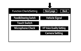
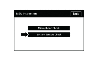
(d) Select "MEU Inspection" from the "Function Check/Setting 2" screen.
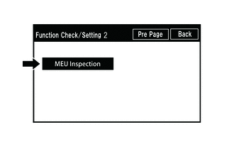
(e) Select "System Sensors Check" from the "MEU Inspection" screen.
(f) System Sensors Check
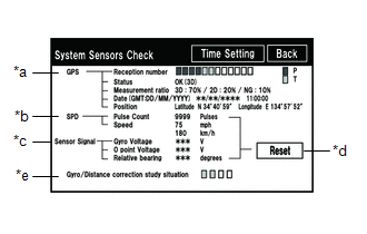 *a: GPS
|
Display |
Content |
||
|---|---|---|---|
|
Reception number |
Displays reception condition of the satellites used to determine vehicle position |
Blue: P (In use) |
System is using GPS signal for location. |
|
Yellow: T (Receiving) |
System is tracking GPS signal for location. |
||
|
No color: Not in use |
System cannot receive GPS signal. (Searching for GPS signal) |
||
|
Status |
Displays reception status of the satellites used to determine vehicle position |
OK (3D) |
3-dimensional location method is being used. |
|
OK (2D) |
2-dimensional location method is being used. |
||
|
NG |
Location data cannot be used. |
||
|
error |
Reception error has occurred. |
||
|
- |
Any other state. |
||
|
Measurement ratio |
Displays the ratio of satellites performing measurements |
3D |
The ratio of satellites performing 3D positioning is displayed. |
|
2D |
The ratio of satellites performing 2D positioning is displayed. |
||
|
NG |
The ratio of satellites not performing measurement is displayed. |
||
|
Date |
Date/time information obtained from GPS signals is displayed in Greenwich Mean Time (GMT). |
||
|
Position |
Latitude and longitude information on current position is displayed. |
||
|
Display |
Content |
|---|---|
|
Pulse Count |
Displays the accumulated number of input pulses beginning when this screen is displayed |
|
Speed |
Displays vehicle speed |
|
Display |
Content |
Note |
|---|---|---|
|
Gyro Voltage |
Displays the output voltage of the gyro sensor |
- |
|
0 point Voltage |
Displays the zero-point voltage of the gyro sensor |
- |
|
Relative bearing |
Displays the output angle of the gyro sensor |
The amount of change in bearing angle (degrees) after the system sensor check screen is displayed (clockwise: "+", counterclockwise: "-"). |
|
Display |
Content |
|---|---|
|
Reset |
When this switch is pressed and held for 3 seconds or more, the values for the display items of SPD signal and gyro sensor signal are reset and display "0". |
|
Display |
Content |
|---|---|
|
Gyro/Distance correction study situation |
Displays learning status of Gyro/Distance correction |
(1) When the "System Sensors Check" screen is displayed, check all the sensor signals.
HINT:
This screen is updated once per second.
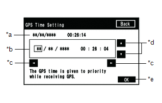
(g) GPS Time Setting
 Screen Description
|
Display |
Content |
|---|---|
|
*a: Time display |
Displays the date and time in the device. |
|
*b: Date and time setting screen |
Setting is possible only when GPS signals are not being received. |
|
*c: Cursor movement switch |
Moves the cursor on the date and time setting screen to the right and left. |
|
*d: Adjustment switch |
Adjusts values of items selected by the cursor. |
|
*e: OK switch |
Selecting this switch after setting the date and time updates the date and time in the device (only when GPS signals are not received). |
(1) When GPS signals are not being received, the data and time in the device can be adjusted.
HINT:
Time setting is possible only when GPS signals are not being received. When the audio and visual system (for Radio and Display Type) is receiving GPS signals, priority is given to displaying the time and date received via GPS.
CHECK VEHICLE SIGNAL
HINT:
- Vehicle signals received by the radio and display receiver assembly are checked in the following procedure.
- Illustrations may differ from the actual vehicle screen depending on the device settings and options. Therefore, some detailed areas may not be shown exactly the same as on the actual vehicle screen.
(a) Enter diagnostic mode.
Click here
(b) Select "Function Check/Setting" from the "Service Menu" screen.
(c) Select "Vehicle Signal" from the "Function Check/Setting I" screen.
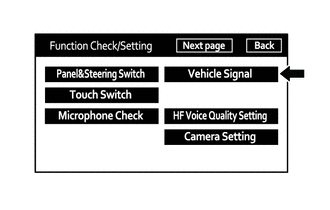
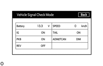
(d) Vehicle Signal Check Mode
 Screen Description
|
Display |
Content |
|---|---|
|
Battery |
Battery voltage is displayed. |
|
IG |
Ignition switch ON/OFF state is displayed. |
|
PKB |
Parking brake ON/OFF state is displayed. |
|
REV |
Reverse signal ON/OFF state is displayed. |
|
SPEED |
Vehicle speed is displayed in km/h. |
|
TAIL |
Tail signal (light control switch) ON/OFF state is displayed. |
|
ADIM/TCAN |
Brightness state DIM (with)/BRIGHT (without) is displayed. |
HINT:
- Only items sending vehicle signals will be displayed.
- This screen displays vehicle signals input to the radio and display receiver assembly.
(1) When the "Vehicle Signal Check Mode" screen is displayed, check all the vehicle signal conditions.
NOTICE:
- These settings are adjusted separately for each registered cellular phone.
- If a cellular phone has not been registered, the settings cannot be adjusted.
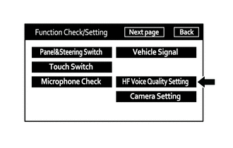
CHECK HANDS-FREE VOICE QUALITY AND VOLUME SETTING
HINT:
- The hands-free voice quality of a "Bluetooth" compatible phone can be adjusted using the following procedure.
- Illustrations may differ from the actual vehicle screen depending on the device settings and options. Therefore, some detailed areas may not be shown exactly the same as on the actual vehicle screen.
(a) Enter diagnostic mode.
Click here
(b) Select "Function Check/Setting" from the "Service Menu" screen.
(c) Select "HF Voice Quality Setting" from the "Function Check/Setting I" screen.
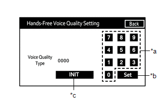
(d) Hands-Free Voice Quality Setting (Voice Quality Type adjustment)
|
*a |
Numeric Keypad |
|
*b |
Setting Button |
|
*c |
Reset Button |
(1) If necessary, refer to the table below to adjust the voice quality type with the numeric keypad.
(2) When adjusting the settings, use the number pad on the screen to input the voice quality type according to the table.
Settings|
Parameter |
Target Phenomenon |
Voice Quality Type |
Positive Effect of Changing Voice Quality |
Negative Effect of Changing Voice Quality |
|---|---|---|---|---|
|
A (Noise) |
The other party hears background noise when listening to your voice. |
1000 |
The amount of background noise the other party hears when listening to your voice is reduced. |
The volume of voice the other party hears when listening to your voice may temporarily drop. |
|
B (Noise) |
The other party hears a lot of background noise when listening to your voice. |
2000 |
The amount of background noise the other party hears when listening to your voice is sharply reduced. |
The volume of voice the other party hears when listening to your voice may temporarily drop. |
|
C (Echo) |
The other party hears weak echoes. |
0100 |
The amount of echo is reduced (low level). |
Sound quality of the other party deteriorates (low level). |
|
D (Echo) |
The other party hears strong echoes. |
0200 |
The amount of echo is reduced (high level). |
Sound quality of the other party deteriorates (high level). |
|
Parameter |
Target Phenomenon |
Voice Quality Type |
Positive Effect of Changing Voice Quality |
Negative Effect of Changing Voice Quality |
|---|---|---|---|---|
|
A+C |
The other party hears background noise and weak echoes when listening to your voice. |
1100 |
|
|
|
A+D |
The other party hears background noise and strong echoes when listening to your voice. |
1200 |
|
|
|
B+C |
The other party hears a lot of background noise and weak echoes when listening to your voice. |
2100 |
|
|
|
B+D |
The other party hears a lot of background noise and strong echoes when listening to your voice. |
2200 |
|
|
HINT:
- The default value is "0000".
- Settings will be applied when the setting button is selected.
- If voice quality type values that are not in the table are input, the setting will not be applied and a positive effect may not be gained.
- If the quality of phone calls decreases due to the changed settings, return the settings to "0000" by selecting "INIT".
CHECK SPEAKER
HINT:
- This function is used when checking the speaker wiring and whether the speakers are functioning properly.
- Illustrations may differ from the actual vehicle screen depending on the device settings and options. Therefore, some detailed areas may not be shown exactly the same as on the actual vehicle screen.
(a) Turn audio mode on and play any audio source.
HINT:
This audio source will be used for the speaker check.
(b) Enter diagnostic mode.
Click here
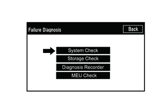
(c) Select "Failure Diagnosis" from the "Service Menu" screen.
(d) Select "System Check" from the "Failure Diagnosis" screen.
(e) Select "SPCheck ON" from the "System Check Mode" screen.
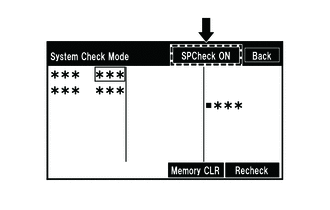
(f) Check the speaker wiring and check that the speakers are functioning properly.
HINT:
- Check that each speaker outputs sound from the selected audio source properly.
- "SPCheck OFF" is displayed during the speaker check.
- Sound can be heard from the speakers around the vehicle in order beginning from a speaker on the front side.
- More than one speaker may sound simultaneously depending on the speaker wiring.
- The sounding order during SPCheck cannot be adjusted.
(g) Sound stops when any of the following conditions are met:
(1) "SPCheck OFF" is selected.
(2) The ignition switch is turned off.
(3) Diagnostic mode is turned off.
(4) The screen is changed to another screen.
(5) Audio mode is turned off.
CHECK SOFTWARE ERROR HISTORY
HINT:
- This function is used to check the cause when the radio and display receiver assembly screen is blacked out.
- Existence of error history can be confirmed, but the malfunction location cannot be determined.
(a) Check Software Error History.
(1) Connect the Techstream to the DLC3.
(2) Turn the ignition switch to ON.
(3) Turn the Techstream on.
(4) Enter the following menus: Body Electrical / Navigation System / Utility / Software Error History.
Body Electrical > Navigation System > Utility|
Tester Display |
|---|
|
Software Error History |
(5) When an item is stored for Software Error History, record it before repairing the radio and display receiver assembly.
Software Error History Screen Description|
Error Description |
Trigger |
|---|---|
|
Software Reset |
Navi Microcomputer |
|
Audio Microcomputer |
|
|
CAN Microcomputer |
|
|
No Video Signal |
Front Monitor |
|
Rear Monitor |
|
|
MOST Cold Restart |
Always |
HINT:
- The trigger detects malfunctions and displays the location where the malfunction information was stored.
- Software Error History can store up to 5 history data items. If a new software error occurs when 5 data items have already been stored, the oldest data is cleared and the new data is stored.
- If an error that is unsupported by the Techstream occurs, a "-" is displayed for the display items.
(b) Clear software error history.
(1) When DTCs are cleared using any of the following operations, Software Error History will be cleared as well.
Click here
- Cleared using the Techstream.
- Cleared using the system check mode screen.
- Cleared using the unit check mode screen.
CHECK "Bluetooth" CONNECTION HISTORY
HINT:
This function is used to check the connection history when the connection between the radio and display receiver assembly and a "Bluetooth" device is unstable.
(a) Check "Bluetooth" Connection History.
HINT:
- "Bluetooth" Connection History displays data stored in the internal memory of the ECU, such as the date a "Bluetooth" connection was attempted and the state of a "Bluetooth" connection.
- By checking "Bluetooth" Connection History, the date, cause, etc. of a "Bluetooth" device failing to register or connect can be analyzed.
- "Bluetooth" connection history indicates the estimated cause of a malfunction, but does not determine it. Therefore, checking "Bluetooth" Connection History may not improve the problem.
- Performing an inspection using the Techstream before recording the "Bluetooth" Connection History may clear the history.
(1) Connect the USB memory device to the No. 1 stereo jack adapter assembly.
(2) Enter diagnostic mode.
Click here
(3) Select "Failure Diagnosis" from the "Service Menu" screen.
(4) Select "Diagnosis Recorder" from the "Failure Diagnosis" screen.
(5) Push the "Recording ON/OFF" switch to enable "BT Communication Trace output" to be selected.
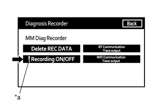
|
*a |
Green indicator |
HINT:
When the green "Recording ON/OFF" indicator is illuminated, the "BT Communication Trace output" is grayed out and cannot be selected.
(6) Select "BT Communication Trace output" for 3 seconds.
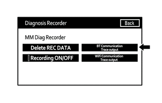
(7) According to the instructions on the screen, save the "Bluetooth" Connection History data to a USB memory device.
(8) Select "Recording ON/OFF" on the Diagnosis Recorder screen to illuminate the green "Recording ON/OFF" indicator.
HINT:
Make sure that the green "Recording ON/OFF" indicator returns to illuminated state, after performing the above procedure.
(9) Connect the USB memory device with the saved "Bluetooth" connection history data to the Techstream.
(10) Turn the Techstream on.
(11) Enter the following menus: Advanced Function / Bluetooth Connection History.
(12) According to the Techstream screen, select the saved "Bluetooth" Connection History file.
(13) According to the Techstream screen, select the saved "Bluetooth" Connection History file.
"Bluetooth" Connection History Screen Description|
Item |
Content |
|---|---|
|
Occurrence Start Date/Time |
Date and time of "Bluetooth" connection are displayed. |
|
Occurrence End Date/Time |
Date and time of "Bluetooth" disconnection are displayed. |
|
History Type |
Type of "Bluetooth" Connection History is displayed. |
|
Result |
"Bluetooth" connection result is displayed. |
|
Contents |
"Bluetooth" connection status is displayed. |
|
"Bluetooth" Address |
"Bluetooth" device address is displayed. |
|
Continuance Time |
The number of retries when "Bluetooth" connection was performed is displayed. |
|
Result |
Contents |
Detail |
Areas to be Checked |
|---|---|---|---|
|
- |
- |
Ignition switch is ACC |
- |
|
Result |
Contents |
Detail |
Areas to be Checked |
|---|---|---|---|
|
Success (HFP) |
No Error |
"Bluetooth" device was registered as a hands-free device properly. |
- |
|
Success (AVP) |
No Error |
"Bluetooth" device was registered as a "Bluetooth" audio device properly. |
- |
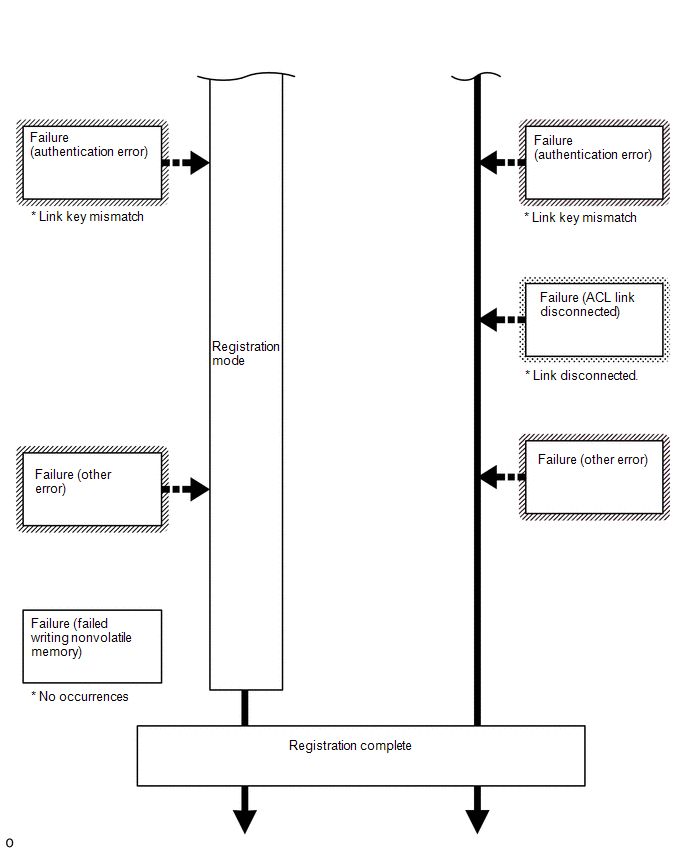
|
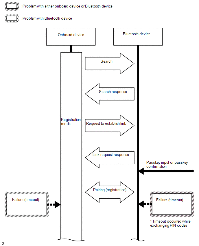
Failure |
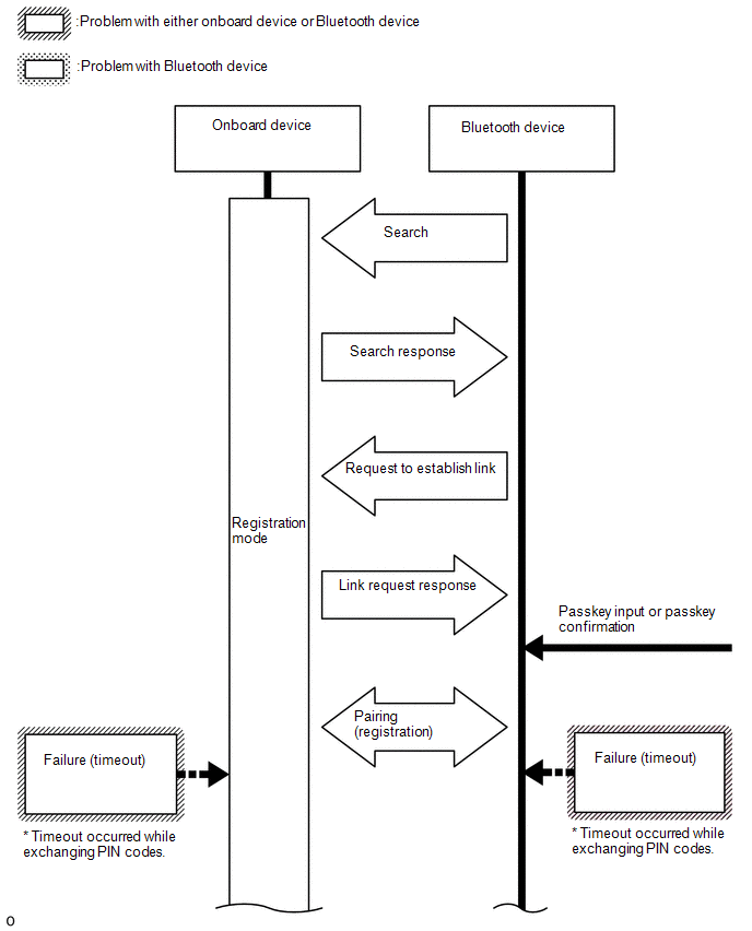
Time Out |
"Bluetooth" connection could not be established properly. |
|
|
Authentication Error |
Wrong PIN code was input for PIN code verification. |
Perform "Bluetooth" device registration again. (Input PIN code correctly.) |
|
|
Confirmation button was not selected even though a passkey was displayed. |
Perform "Bluetooth" device registration again. (When a passkey is displayed, select the confirmation button.) |
||
|
A verification error occurred between the radio and display receiver assembly and "Bluetooth" device. |
Restart the radio and display receiver assembly and "Bluetooth" device, and operate them again. |
||
|
ACL Link Disconnection |
"Bluetooth" connection was disconnected by operating the "Bluetooth" device. |
Perform "Bluetooth" device registration again. |
|
|
"Bluetooth" connection could not be established due to wave interference around the vehicle. |
Check for wave interference and perform "Bluetooth" device registration again. |
||
|
"Bluetooth" device was outside the communication area. |
Bring the "Bluetooth" device near the radio and display receiver assembly and perform "Bluetooth" device registration again. |
||
|
"Bluetooth" setting on the "Bluetooth" device was off. |
Change the "Bluetooth" setting to on and perform "Bluetooth" device registration again. |
||
|
"Bluetooth" device was off. |
Turn the "Bluetooth" device on and perform "Bluetooth" device registration again. |
||
|
Memory Write Failure |
"Bluetooth" device information could not be stored in the radio and display receiver assembly. |
Perform "Bluetooth" device registration again. |
|
|
Other Error |
An error other than above occurred. |
After turning the ignition switch off and back to on (IG) again, perform "Bluetooth" device registration again. |
|
|
Cancel |
No Error |
Registration was suspended by operating the radio and display receiver assembly or "Bluetooth" device. |
- |
|
Result |
Contents |
Detail |
Areas to be Checked |
|---|---|---|---|
|
No Error |
"Bluetooth" device was connected as a hands-free device properly. |
- |
|
Time Out |
"Bluetooth" connection could not be established properly. |
|
|
Authentication Error |
Verification of authentication key between the radio and display receiver assembly and "Bluetooth" device failed. |
If "Bluetooth" connection fails multiple times, perform registration again. |
|
|
A verification error occurred between the radio and display receiver assembly and "Bluetooth" device. |
Restart the radio and display receiver assembly and "Bluetooth" device, and operate them again. |
||
|
Page Time Out |
Could not find a "Bluetooth" device near the radio and display receiver assembly. |
Bring the "Bluetooth" device near the radio and display receiver assembly and perform "Bluetooth" connection again. |
|
|
"Bluetooth" connection could not be established due to wave interference around the vehicle. |
Check for wave interference and perform "Bluetooth" connection again. |
||
|
"Bluetooth" device was outside the communication area. |
Bring the "Bluetooth" device near the radio and display receiver assembly and perform "Bluetooth" connection again. |
||
|
"Bluetooth" setting on the "Bluetooth" device was off. |
Change the "Bluetooth" setting to on and perform "Bluetooth" connection again. |
||
|
"Bluetooth" device was off. |
Turn the "Bluetooth" device on and perform "Bluetooth" connection again. |
||
|
A malfunction of the "Bluetooth" device occurred. |
Restart the "Bluetooth" device and operate it again. |
|
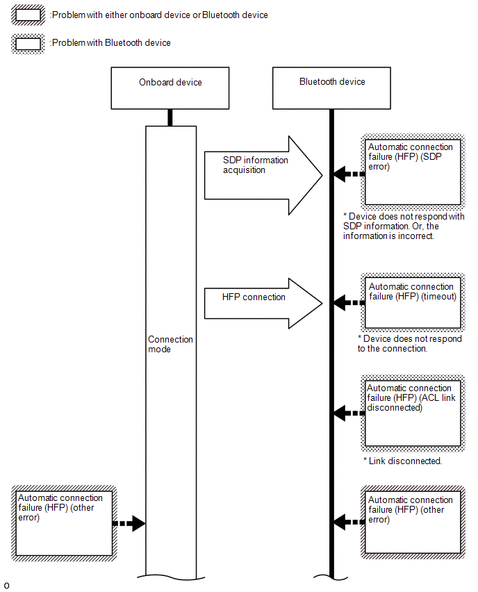
Result |
Contents |
Detail |
Areas to be Checked |
|---|---|---|---|
|
ACL Link Disconnection |
"Bluetooth" connection was disconnected by operating the "Bluetooth" device. |
Perform "Bluetooth" connection again. |
|
"Bluetooth" connection could not be established due to wave interference around the vehicle. |
Check for wave interference and perform "Bluetooth" connection again. |
||
|
"Bluetooth" device was outside the communication area. |
Bring the "Bluetooth" device near the radio and display receiver assembly and perform "Bluetooth" connection again. |
||
|
"Bluetooth" setting on the "Bluetooth" device was off. |
Change the "Bluetooth" setting to on and perform "Bluetooth" connection again. |
||
|
"Bluetooth" device was off. |
Turn the "Bluetooth" device on and perform "Bluetooth" connection again. |
||
|
A malfunction of the "Bluetooth" device occurred. |
Restart the "Bluetooth" device and operate it again. |
||
|
SDP Error |
HFP was disabled on the "Bluetooth" device. |
Enable HFP on the "Bluetooth" device and perform "Bluetooth" connection again. |
|
|
"Bluetooth" device which operation had not been confirmed was used. |
Check that the "Bluetooth" device is hands-free compatible and its operation has been confirmed.
|
||
|
Other Error |
An error other than above occurred. |
After turning the ignition switch off and back to on (IG) again, perform "Bluetooth" device registration again. |
|
|
Manual Connect Cancel (HFP) |
No Error |
Connection was interrupted by operating the radio and display receiver assembly or "Bluetooth" device. |
- |
|
Result |
Contents |
Detail |
Areas to be Checked |
|---|---|---|---|
|
No Error |
"Bluetooth" device was connected as a "Bluetooth" audio device properly. |
- |
|
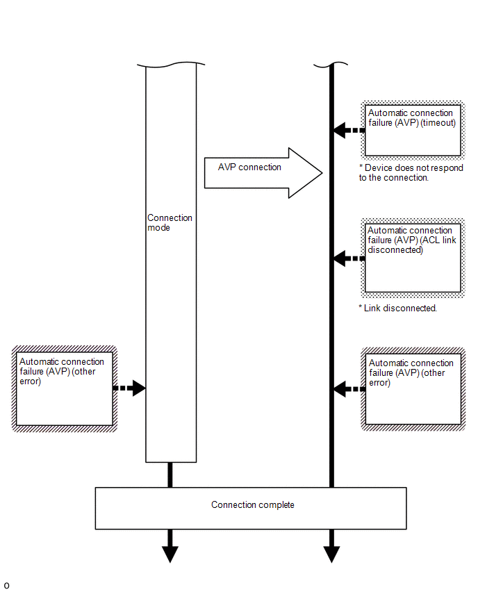
Time Out |
"Bluetooth" connection could not be established properly. |
|
|
Authentication Error |
Verification of authentication key between the radio and display receiver assembly and "Bluetooth" device failed. |
If "Bluetooth" connection fails multiple times, perform registration again. |
|
|
A verification error occurred between the radio and display receiver assembly and "Bluetooth" device. |
Restart the radio and display receiver assembly and "Bluetooth" device, and operate them again. |
||
|
Page Time Out |
Could not find a "Bluetooth" device near the radio and display receiver assembly. |
Bring the "Bluetooth" device near the radio and display receiver assembly and perform "Bluetooth" connection again. |
|
|
"Bluetooth" connection could not be established due to wave interference around the vehicle. |
Check for wave interference and perform "Bluetooth" connection again. |
||
|
"Bluetooth" device was outside the communication area. |
Bring the "Bluetooth" device near the radio and display receiver assembly and perform "Bluetooth" connection again. |
||
|
"Bluetooth" setting on the "Bluetooth" device was off. |
Change the "Bluetooth" setting to on and perform "Bluetooth" connection again. |
||
|
"Bluetooth" device was off. |
Turn the "Bluetooth" device on and perform "Bluetooth" connection again. |
||
|
A malfunction of the "Bluetooth" device occurred. |
Restart the "Bluetooth" device and operate it again. |
|
Result |
Contents |
Detail |
Areas to be Checked |
|---|---|---|---|
|
ACL Link Disconnection |
"Bluetooth" connection was disconnected by operating the "Bluetooth" device. |
Perform "Bluetooth" connection again. |
|
"Bluetooth" connection could not be established due to wave interference around the vehicle. |
Check for wave interference and perform "Bluetooth" connection again. |
||
|
"Bluetooth" device was outside the communication area. |
Bring the "Bluetooth" device near the radio and display receiver assembly and perform "Bluetooth" connection again. |
||
|
"Bluetooth" setting on the "Bluetooth" device was off. |
Change the "Bluetooth" setting to on and perform "Bluetooth" connection again. |
||
|
"Bluetooth" device was off. |
Turn the "Bluetooth" device on and perform "Bluetooth" connection again. |
||
|
A malfunction of the "Bluetooth" device occurred. |
Restart the "Bluetooth" device and operate it again. |
||
|
SDP Error |
AVP was disabled on the "Bluetooth" device. |
Enable AVP on the "Bluetooth" device and perform "Bluetooth" connection again. |
|
|
"Bluetooth" device which operation had not been confirmed was used. |
Check that the "Bluetooth" device is "Bluetooth" audio compatible and its operation has been confirmed.
|
||
|
Other Error |
An error other than above occurred. |
After turning the ignition switch off and back to on (IG) again, perform "Bluetooth" device registration again. |
|
|
Manual Connect Cancel (AVP) |
No Error |
Connection was interrupted by operating the radio and display receiver assembly or "Bluetooth" device. |
- |
|
Result |
Contents |
Detail |
Areas to be Checked |
|---|---|---|---|
|
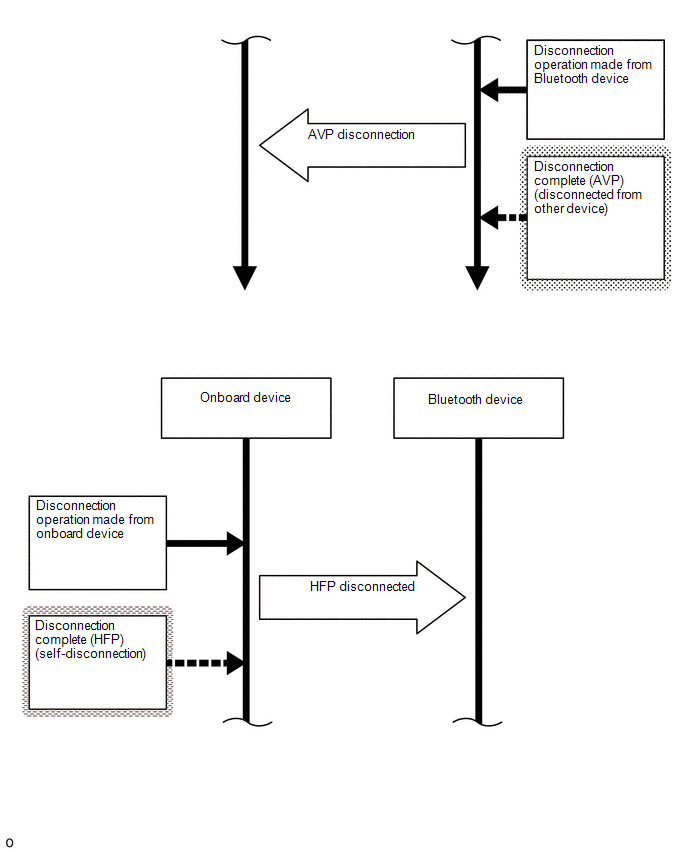
Disconnection Complete (HFP) |
Link Loss |
The "Bluetooth" device was moved outside of the communication area. |
Move the "Bluetooth" device into the communication area. |
|
"Bluetooth" connection was disconnected due to wave interference around the vehicle. |
Check for wave interference and perform "Bluetooth" connection again. |
||
|
A malfunction of the "Bluetooth" device occurred. |
Restart the "Bluetooth" device and operate it again. |
||
|
Disconnection from Partner |
"Bluetooth" connection was disconnected by operating the "Bluetooth" device. |
- |
|
|
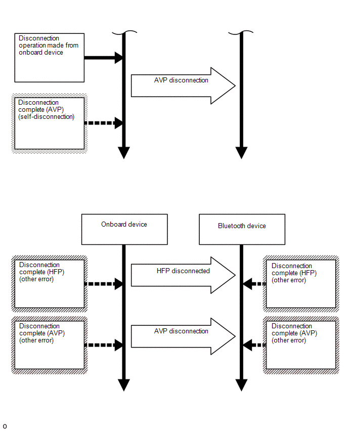
Disconnection from Self |
"Bluetooth" connection was disconnected by operating the radio and display receiver assembly. |
- |
|
|
Other Error |
An error other than above occurred. |
After turning the ignition switch off and back to on (IG) again, perform "Bluetooth" device registration again. |
|
|
Disconnection Complete (AVP) |
Link Loss |
The "Bluetooth" device was moved outside of the communication area. |
Move the "Bluetooth" device into the communication area. |
|
"Bluetooth" connection was disconnected due to wave interference around the vehicle. |
Check for wave interference and perform "Bluetooth" connection again. |
||
|
A malfunction of the "Bluetooth" device occurred. |
Restart the "Bluetooth" device and operate it again. |
||
|
Disconnection from Partner |
"Bluetooth" connection was disconnected by operating the "Bluetooth" device. |
- |
|
|
Disconnection from Self |
"Bluetooth" connection was disconnected by operating the radio and display receiver assembly. |
- |
|
|
Other Error |
An error other than above occurred. |
After turning the ignition switch off and back to on (IG) again, perform "Bluetooth" device registration again. |
|
Result |
Contents |
Detail |
Areas to be Checked |
|---|---|---|---|
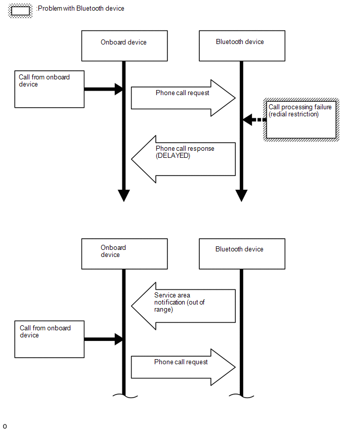
|
Success |
No Error |
Call was made properly. |
- |
|
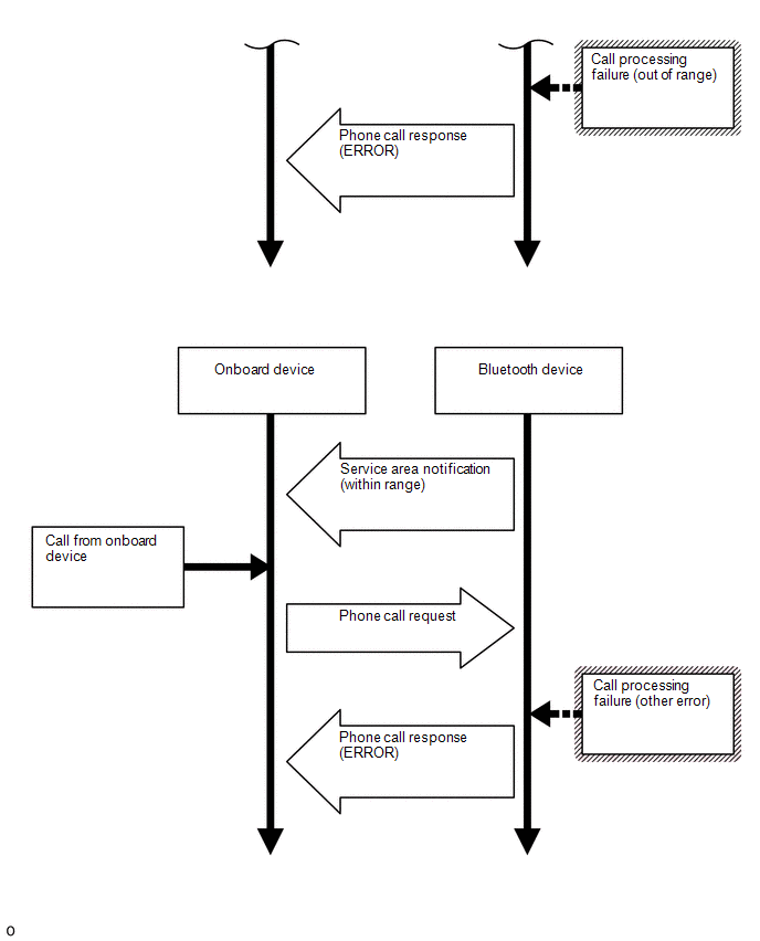
Failure |
Out of Service |
Outside the cellular phone service area. |
Move the vehicle into a cellular phone service area, check that the "Bluetooth" device is connected to the vehicle and operate the device again. |
|
Redial Regulation |
Redial of the "Bluetooth" device was restricted and could not make a hands-free call. |
Restart the "Bluetooth" device and operate it again. |
|
|
Other Error |
Could not make a hands-free call due to a "Bluetooth" device malfunction. |
Restart the "Bluetooth" device and operate it again. |
|
|
Could not make a hands-free call due to a radio and display receiver assembly malfunction. |
After turning the ignition switch off and back to on (IG) again, perform "Bluetooth" device registration again. |
||
|
Could not make a hands-free call from the radio and display receiver assembly because the call status of the "Bluetooth" device was not transmitted to the radio and display receiver assembly. |
Restart the "Bluetooth" device and operate it again. |
HINT:
The names of items in the Result and Contents columns of the table may differ from the actual item displayed on the Techstream.
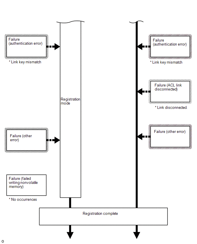
Bluetooth Connection Sequence (Registration from onboard device)
Bluetooth Connection Sequence (Connection from onboard device after registration)
Bluetooth Connection Sequence (Registration from Bluetooth device)
Bluetooth Connection Sequence (Connection from Bluetooth device after registration)
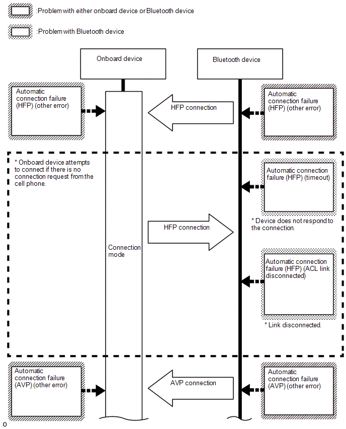
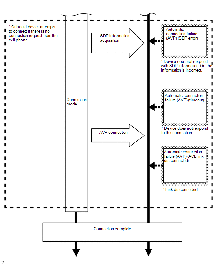
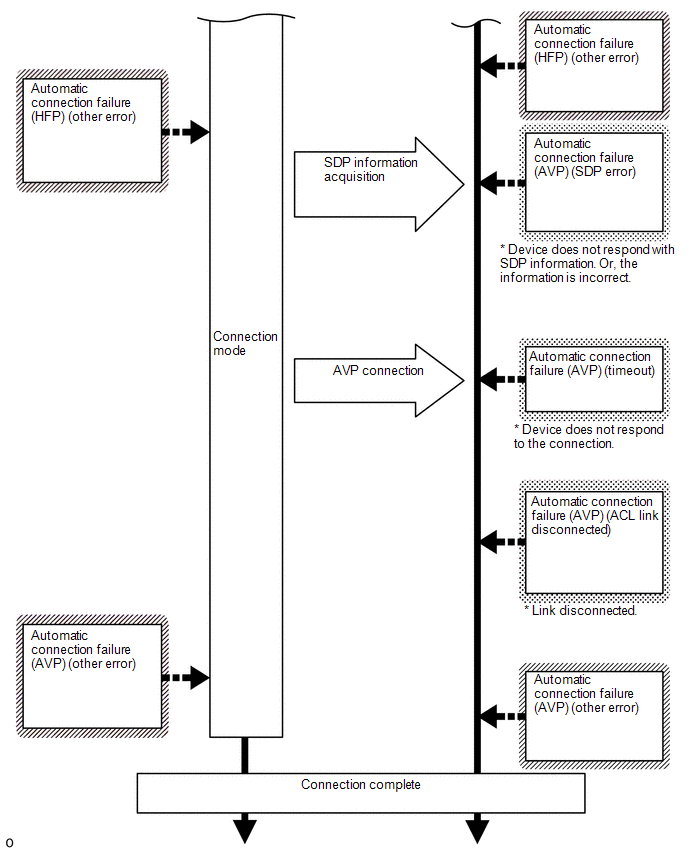
Bluetooth Connection Sequence (Automatic Connection)
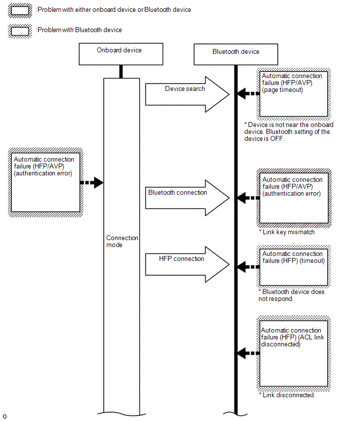
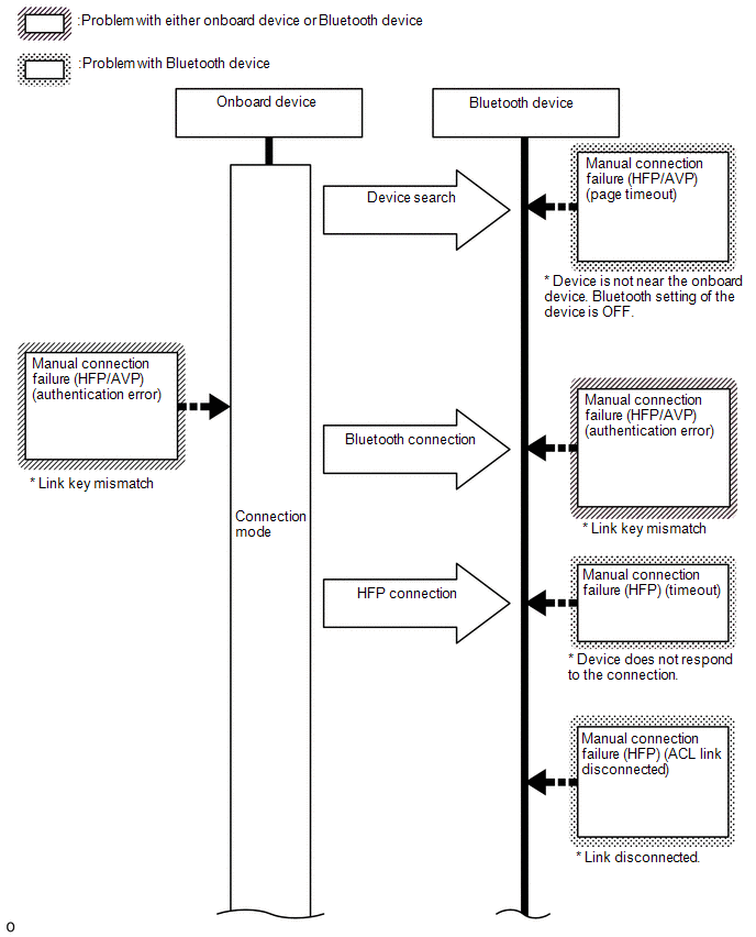
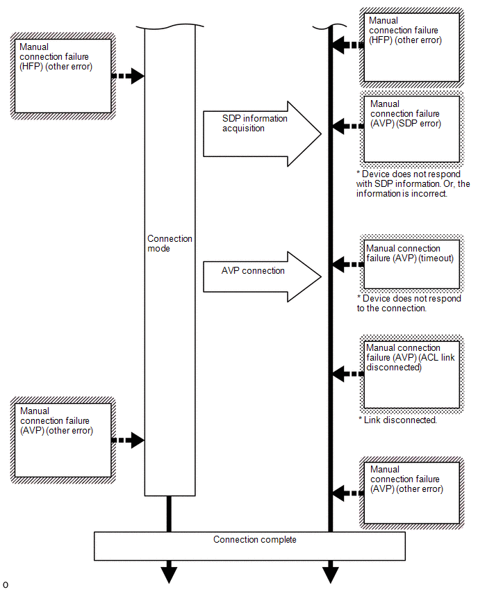
Bluetooth Connection Sequence (Manual Connection)
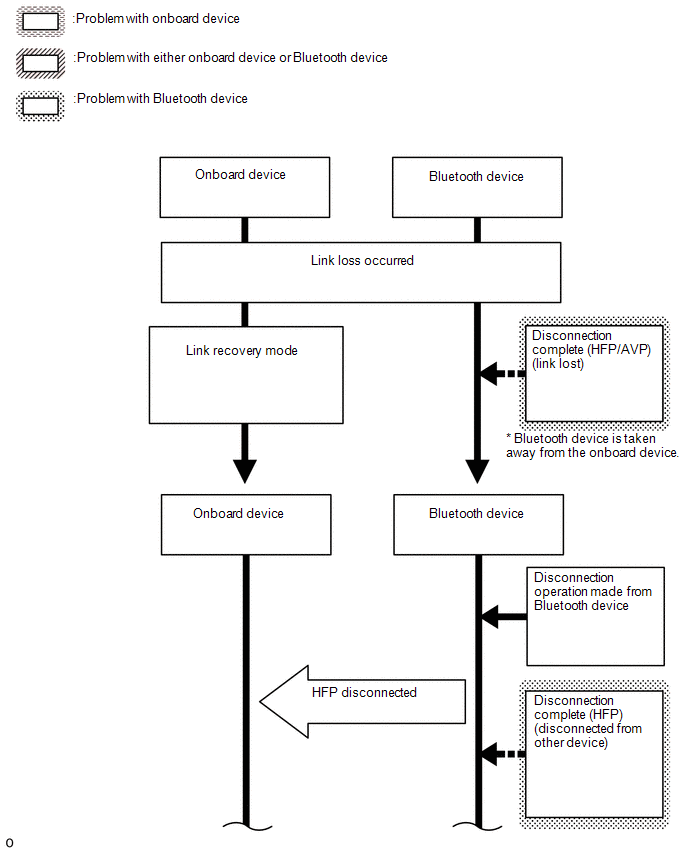
Bluetooth Connection Sequence (Disconnection Processing)
Bluetooth Connection Sequence (Phone Call Processing)
HINT:
Bluetooth Related Terms:
|
Marking in Repair Manual |
Description |
|
|---|---|---|
|
HFP |
(Hands Free Profile) |
Profile for making and receiving telephone calls. |
|
AVP |
(Audio/Video Profile) |
Profile for music playback, lyric display and operation. |
|
ACL |
(Asynchronous Connection Less) |
One of the Bluetooth connection methods used for data transfer. |
|
SDP |
(Service Discovery Protocol) |
Protocol used to determine what kind of service is supported by the connected device. |
 How To Proceed With Troubleshooting
CAUTION / NOTICE / HINT
HINT:
Use the following procedure to troubleshoot the audio and visual system.
*: Use the Techstream.
PROCEDURE
1.
VEHICLE BROUG ...
 Problem Symptoms Table
PROBLEM SYMPTOMS TABLE
NOTICE:
When replacing the radio and display receiver assembly or navigation
ECU, always replace it with a new one. If a radio and display receiver assembly
or ...
Other materials:
Toyota CH-R Service Manual > Power Window Control System: Glass Position Initialization Incomplete (B2313)
DESCRIPTION
The power window regulator motor assemblies are operated by the multiplex network
master switch assembly, power window regulator switch assembly or rear power window
regulator switch assemblies. The power window regulator motor assembly has motor,
regulator and ECU functions.
Whe ...
Toyota CH-R Service Manual > Rear Shock Absorber: Components
COMPONENTS
ILLUSTRATION
*1
REAR SHOCK ABSORBER ASSEMBLY
*2
REAR STABILIZER LINK ASSEMBLY
*3
REAR UPPER CONTROL ARM ASSEMBLY
*4
REAR STABILIZER BAR
Tightening torque for "M ...
Toyota C-HR (AX20) 2023-2026 Owner's Manual
Toyota CH-R Owners Manual
- For safety and security
- Instrument cluster
- Operation of each component
- Driving
- Interior features
- Maintenance and care
- When trouble arises
- Vehicle specifications
- For owners
Toyota CH-R Service Manual
- Introduction
- Maintenance
- Audio / Video
- Cellular Communication
- Navigation / Multi Info Display
- Park Assist / Monitoring
- Brake (front)
- Brake (rear)
- Brake Control / Dynamic Control Systems
- Brake System (other)
- Parking Brake
- Axle And Differential
- Drive Shaft / Propeller Shaft
- K114 Cvt
- 3zr-fae Battery / Charging
- Networking
- Power Distribution
- Power Assist Systems
- Steering Column
- Steering Gear / Linkage
- Alignment / Handling Diagnosis
- Front Suspension
- Rear Suspension
- Tire / Wheel
- Tire Pressure Monitoring
- Door / Hatch
- Exterior Panels / Trim
- Horn
- Lighting (ext)
- Mirror (ext)
- Window / Glass
- Wiper / Washer
- Door Lock
- Heating / Air Conditioning
- Interior Panels / Trim
- Lighting (int)
- Meter / Gauge / Display
- Mirror (int)
- Power Outlets (int)
- Pre-collision
- Seat
- Seat Belt
- Supplemental Restraint Systems
- Theft Deterrent / Keyless Entry

0.0091