Toyota CH-R Service Manual: Vehicle Speed Signal Circuit between Radio Receiver and Combination Meter
DESCRIPTION
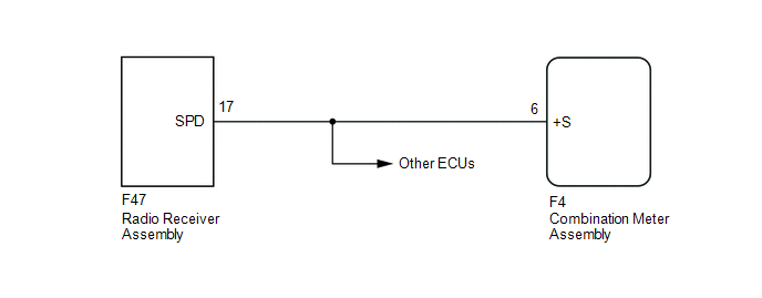
- This circuit is necessary for the Automatic Sound Levelizer (ASL) built
into the radio receiver assembly.
The Automatic Sound Levelizer (ASL) function automatically adjusts the audio system volume level in order to compensate for increased vehicle noise (vehicle noise tends to increase as vehicle speed increases). The ASL adjusts the volume level based upon vehicle speed signals sent from the combination meter assembly.
- Vehicle speed signals are received from the combination meter assembly
and used to cancel "Bluetooth" function operation.
The radio receiver assembly recognizes that the vehicle is being driven and makes it impossible to connect or register a "Bluetooth" device while driving.
HINT:
- A voltage of 12 V or 5 V is output from each ECU and then input to the combination meter assembly. The signal is changed to a pulse signal at the transistor in the combination meter assembly. Each ECU controls its respective system based on this pulse signal.
- If a short occurs in any of the ECUs or in the wire harness connected to an ECU, all systems in the following diagram will not operate normally.
WIRING DIAGRAM
PROCEDURE
|
1. |
INSPECT COMBINATION METER ASSEMBLY (OUTPUT WAVEFORM) |
(a) Check the output waveform.
|
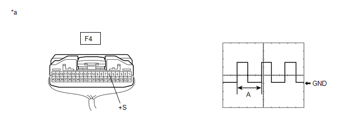
*a |
Component with harness connected (Combination Meter Assembly) |
- |
- |
(1) Remove the combination meter assembly with the connector still connected.
(2) Connect an oscilloscope to terminal F4-6 (+S) and body ground.
(3) Turn the ignition switch to ON.
(4) Turn a wheel slowly.
(5) Check the signal waveform according to the condition(s) in the table below.
|
Item |
Condition |
|---|---|
|
Measurement terminal |
F4-6 (+S) - Body ground |
|
Tool setting |
5 V/DIV., 20 ms./DIV. |
|
Vehicle condition |
Wheel being rotated |
OK:
The waveform is similar to that shown in the illustration.
HINT:
When the system is functioning normally, one wheel revolution generates 4 pulses. As the vehicle speed increases, the width indicated by (A) in the illustration narrows.
| NG | .gif) |
GO TO METER / GAUGE / DISPLAY |
|
.gif)
|
2. |
INSPECT RADIO RECEIVER ASSEMBLY (INPUT WAVEFORM) |
(a) Check the output waveform.
|
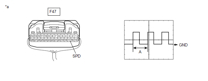
*a |
Component with harness connected (Radio Receiver Assembly) |
- |
- |
(1) Remove the combination meter assembly with the connector still connected.
(2) Connect an oscilloscope to terminal F47-17 (SPD) and body ground.
(3) Turn the ignition switch to ON.
(4) Turn a wheel slowly.
(5) Check the signal waveform according to the condition(s) in the table below.
|
Item |
Condition |
|---|---|
|
Measurement terminal |
F47-17 (SPD) - Body ground |
|
Tool setting |
5 V/DIV., 20 ms./DIV. |
|
Vehicle condition |
Wheel being rotated |
OK:
The waveform is similar to that shown in the illustration.
HINT:
When the system is functioning normally, one wheel revolution generates 4 pulses. As the vehicle speed increases, the width indicated by (A) in the illustration narrows.
| OK | |
REPLACE RADIO RECEIVER ASSEMBLY |
|
|
3. |
CHECK HARNESS AND CONNECTOR (RADIO RECEIVER ASSEMBLY - COMBINATION METER ASSEMBLY) |
(a) Disconnect the F47 radio receiver assembly connector.
(b) Disconnect the F4 combination meter assembly connector.
(c) Measure the resistance according to the value(s) in the table below.
Standard Resistance:
|
Tester Connection |
Condition |
Specified Condition |
|---|---|---|
|
F47-17 (SPD) - F4-6 (+S) |
Always |
Below 1 Ω |
| OK | |
PROCEED TO NEXT SUSPECTED AREA SHOWN IN PROBLEM SYMPTOMS TABLE |
| NG | |
REPAIR OR REPLACE HARNESS OR CONNECTOR |
 USB Audio System Recognition/Play Error
DESCRIPTION
When a USB device or "iPod" is connected to the USB connector of the radio receiver
assembly, it must have playable files. The device must also communicate with and
be recog ...
 Steering Pad Switch Circuit
DESCRIPTION
This circuit sends an operation signal from the steering pad switch assembly
to the radio receiver assembly.
If there is an open in the circuit, the audio system cannot be operated usi ...
Other materials:
Toyota CH-R Service Manual > Rear Seat Outer Belt Assembly: On-vehicle Inspection
ON-VEHICLE INSPECTION
CAUTION / NOTICE / HINT
CAUTION:
Be sure to correctly follow the removal and installation procedures for the rear
3 point type seat outer belt assembly.
PROCEDURE
1. INSPECT REAR 3 POINT TYPE SEAT OUTER BELT ASSEMBLY (for Vehicle not Involved
in Collision)
(a) Visuall ...
Toyota CH-R Service Manual > Front Stabilizer Bar: Components
COMPONENTS
ILLUSTRATION
*1
FRONT NO. 1 STABILIZER BRACKET LH
*2
FRONT NO. 1 STABILIZER BRACKET RH
*3
FRONT STABILIZER BAR
*4
FRONT STABILIZER BAR BUSHING LH
*5
FRONT STABILIZ ...
Toyota C-HR (AX20) 2023-2026 Owner's Manual
Toyota CH-R Owners Manual
- For safety and security
- Instrument cluster
- Operation of each component
- Driving
- Interior features
- Maintenance and care
- When trouble arises
- Vehicle specifications
- For owners
Toyota CH-R Service Manual
- Introduction
- Maintenance
- Audio / Video
- Cellular Communication
- Navigation / Multi Info Display
- Park Assist / Monitoring
- Brake (front)
- Brake (rear)
- Brake Control / Dynamic Control Systems
- Brake System (other)
- Parking Brake
- Axle And Differential
- Drive Shaft / Propeller Shaft
- K114 Cvt
- 3zr-fae Battery / Charging
- Networking
- Power Distribution
- Power Assist Systems
- Steering Column
- Steering Gear / Linkage
- Alignment / Handling Diagnosis
- Front Suspension
- Rear Suspension
- Tire / Wheel
- Tire Pressure Monitoring
- Door / Hatch
- Exterior Panels / Trim
- Horn
- Lighting (ext)
- Mirror (ext)
- Window / Glass
- Wiper / Washer
- Door Lock
- Heating / Air Conditioning
- Interior Panels / Trim
- Lighting (int)
- Meter / Gauge / Display
- Mirror (int)
- Power Outlets (int)
- Pre-collision
- Seat
- Seat Belt
- Supplemental Restraint Systems
- Theft Deterrent / Keyless Entry

0.0068